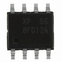
Z8F012ASB020SG Zilog, Z8F012ASB020SG Datasheet - Page 243

Z8F012ASB020SG
Manufacturer Part Number
Z8F012ASB020SG
Description
IC ENCORE XP MCU FLASH 1K 8SOIC
Manufacturer
Zilog
Series
Encore!® XP®r
Datasheet
1.Z8F011ASB020EG.pdf
(282 pages)
Specifications of Z8F012ASB020SG
Core Processor
Z8
Core Size
8-Bit
Speed
20MHz
Connectivity
IrDA, UART/USART
Peripherals
Brown-out Detect/Reset, LED, LVD, POR, PWM, Temp Sensor, WDT
Number Of I /o
6
Program Memory Size
1KB (1K x 8)
Program Memory Type
FLASH
Eeprom Size
16 x 8
Ram Size
256 x 8
Voltage - Supply (vcc/vdd)
2.7 V ~ 3.6 V
Data Converters
A/D 4x10b
Oscillator Type
Internal
Operating Temperature
0°C ~ 70°C
Package / Case
8-SOIC (3.9mm Width)
Processor Series
Z8F012Ax
Core
eZ8
Data Bus Width
8 bit
Data Ram Size
256 B
Interface Type
UART
Maximum Clock Frequency
20 MHz
Number Of Programmable I/os
6
Number Of Timers
2
Operating Supply Voltage
2.7 V to 3.6 V
Maximum Operating Temperature
+ 70 C
Mounting Style
SMD/SMT
Development Tools By Supplier
Z8F04A08100KITG, Z8F04A28100KITG, ZENETSC0100ZACG, ZENETSC0100ZACG, ZUSBOPTSC01ZACG, ZUSBSC00100ZAC, ZUSBSC00100ZACG
Minimum Operating Temperature
0 C
On-chip Adc
10 bit, 4 Channel
Lead Free Status / RoHS Status
Lead free / RoHS Compliant
Other names
269-4039
Z8F012ASB020SG
Z8F012ASB020SG
- Current page: 243 of 282
- Download datasheet (4Mb)
Table 135. Analog-to-Digital Converter Electrical Characteristics and Timing (Continued)
Symbol Parameter
R
Zin
Vin
Notes
PS022825-0908
S
1. Analog source impedance affects the ADC offset voltage (because of pin leakage) and input settling time.
2. Devices are factory calibrated at V DD = 3.3 V and T A = +30 °C, so the ADC is maximally accurate under these
3. LSBs are defined assuming 10-bit resolution.
4. This is the maximum recommended resistance seen by the ADC input pin.
5. The input impedance is inversely proportional to the system clock frequency.
conditions.
Single-Shot Conversion
Time
Continuous Conversion
Time
Signal Input Bandwidth
Analog Source Impedance
Input Impedance
Input Voltage Range
4
Minimum Typical
(unless otherwise stated)
0.3
10
–
–
–
–
–
0
V
T
DD
A
= 0 °C to +70 °C
= 3.0 V to 3.6 V
10258
5129
256
512
150
10
–
–
Maximum
V
DD
V
500
10
–
–
DD
-1.1
Z8 Encore! XP
System
System
Note:
cycles
cycles
Units Conditions
clock
clock
kHz
MΩ
kΩ
kΩ
kΩ
V
V
Product Specification
All measurements but
temperature sensor
Temperature sensor
measurement
All measurements but
temperature sensor
Temperature sensor
measurement
As defined by -3 dB point
In unbuffered mode
In buffered modes
In unbuffered mode at 20
MHz
In buffered modes
Unbuffered Mode
Buffered Modes
These values define the
range over which the
ADC performs within
spec; exceeding these
values does not cause
damage or instability; see
DC Characteristics
page 222 for absolute pin
voltage limits
Electrical Characteristics
5
®
F082A Series
on
232
Related parts for Z8F012ASB020SG
Image
Part Number
Description
Manufacturer
Datasheet
Request
R

Part Number:
Description:
Communication Controllers, ZILOG INTELLIGENT PERIPHERAL CONTROLLER (ZIP)
Manufacturer:
Zilog, Inc.
Datasheet:

Part Number:
Description:
KIT DEV FOR Z8 ENCORE 16K TO 64K
Manufacturer:
Zilog
Datasheet:

Part Number:
Description:
KIT DEV Z8 ENCORE XP 28-PIN
Manufacturer:
Zilog
Datasheet:

Part Number:
Description:
DEV KIT FOR Z8 ENCORE 8K/4K
Manufacturer:
Zilog
Datasheet:

Part Number:
Description:
KIT DEV Z8 ENCORE XP 28-PIN
Manufacturer:
Zilog
Datasheet:

Part Number:
Description:
DEV KIT FOR Z8 ENCORE 4K TO 8K
Manufacturer:
Zilog
Datasheet:

Part Number:
Description:
CMOS Z8 microcontroller. ROM 16 Kbytes, RAM 256 bytes, speed 16 MHz, 32 lines I/O, 3.0V to 5.5V
Manufacturer:
Zilog, Inc.
Datasheet:

Part Number:
Description:
Low-cost microcontroller. 512 bytes ROM, 61 bytes RAM, 8 MHz
Manufacturer:
Zilog, Inc.
Datasheet:

Part Number:
Description:
Z8 4K OTP Microcontroller
Manufacturer:
Zilog, Inc.
Datasheet:

Part Number:
Description:
CMOS SUPER8 ROMLESS MCU
Manufacturer:
Zilog, Inc.
Datasheet:

Part Number:
Description:
SL1866 CMOSZ8 OTP Microcontroller
Manufacturer:
Zilog, Inc.
Datasheet:

Part Number:
Description:
SL1866 CMOSZ8 OTP Microcontroller
Manufacturer:
Zilog, Inc.
Datasheet:

Part Number:
Description:
OTP (KB) = 1, RAM = 125, Speed = 12, I/O = 14, 8-bit Timers = 2, Comm Interfaces Other Features = Por, LV Protect, Voltage = 4.5-5.5V
Manufacturer:
Zilog, Inc.
Datasheet:

Part Number:
Description:
Manufacturer:
Zilog, Inc.
Datasheet:


