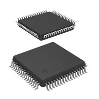
DF36054GFPJ Renesas Electronics America, DF36054GFPJ Datasheet - Page 32

DF36054GFPJ
Manufacturer Part Number
DF36054GFPJ
Description
MCU 3/5V 32K J-TEMP POR&LVD 64-Q
Manufacturer
Renesas Electronics America
Series
H8® H8/300H Tinyr
Datasheet
1.DF36057GFZV.pdf
(594 pages)
Specifications of DF36054GFPJ
Core Processor
H8/300H
Core Size
16-Bit
Speed
20MHz
Connectivity
CAN, SCI, SSU
Peripherals
LVD, POR, PWM, WDT
Number Of I /o
45
Program Memory Size
32KB (32K x 8)
Program Memory Type
FLASH
Ram Size
2K x 8
Voltage - Supply (vcc/vdd)
3 V ~ 5.5 V
Data Converters
A/D 8x10b
Oscillator Type
Internal
Operating Temperature
-40°C ~ 85°C
Package / Case
64-LQFP
Lead Free Status / RoHS Status
Contains lead / RoHS non-compliant
Eeprom Size
-
Other names
HD64F36054GFPJ
HD64F36054GFPJ
HD64F36054GFPJ
- Current page: 32 of 594
- Download datasheet (4Mb)
Table 7.3
Table 7.4
Table 7.5
Table 7.6
Table 7.7
Section 10 Timer B1
Table 10.1
Table 10.2
Section 11 Timer V
Table 11.1
Table 11.2
Section 12 Timer Z
Table 12.1
Table 12.2
Table 12.3
Table 12.4
Table 12.5
Table 12.6
Table 12.7
Table 12.8
Section 14 Serial Communication Interface 3 (SCI3)
Table 14.1
Table 14.2
Table 14.3
Table 14.3
Table 14.3
Table 14.4
Table 14.5
Table 14.5
Table 14.6
Table 14.7
Section 15 Controller Area Network for Tiny (TinyCAN)
Table 15.1
Table 15.2
Table 15.3
Rev. 4.00 Mar. 15, 2006 Page xxx of xxxii
System Clock Frequencies for which Automatic Adjustment of LSI Bit Rate is
Possible................................................................................................................... 98
Reprogram Data Computation Table .................................................................... 102
Additional-Program Data Computation Table ...................................................... 102
Programming Time ............................................................................................... 102
Flash Memory Operating States............................................................................ 107
Pin Configuration.................................................................................................. 144
Timer B1 Operating Modes .................................................................................. 148
Pin Configuration.................................................................................................. 151
Clock Signals to Input to TCNTV and Counting Conditions ............................... 153
Timer Z Functions ................................................................................................ 164
Pin Configuration.................................................................................................. 168
Initial Output Level of FTIOB0 Pin...................................................................... 200
Output Pins in Reset Synchronous PWM Mode................................................... 206
Register Settings in Reset Synchronous PWM Mode........................................... 206
Output Pins in Complementary PWM Mode........................................................ 210
Register Settings in Complementary PWM Mode................................................ 211
Register Combinations in Buffer Operation ......................................................... 221
Channel Configuration.......................................................................................... 252
Pin Configuration.................................................................................................. 254
Examples of BRR Settings for Various Bit Rates (Asynchronous Mode) (1) ...... 262
Examples of BRR Settings for Various Bit Rates (Asynchronous Mode) (2) ...... 264
Examples of BRR Settings for Various Bit Rates (Asynchronous Mode) (3) ...... 266
Maximum Bit Rate for Each Frequency (Asynchronous Mode) .......................... 267
Examples of BRR Settings for Various Bit Rates
(Clocked Synchronous Mode) (1)......................................................................... 268
Examples of BRR Settings for Various Bit Rates
(Clocked Synchronous Mode) (2)......................................................................... 269
SSR Status Flags and Receive Data Handling ...................................................... 275
SCI3 Interrupt Requests........................................................................................ 291
Pin Configuration.................................................................................................. 297
Settable Values in BCR ........................................................................................ 325
Settable Values for TSG1 and TSG2 in BCR1 ..................................................... 326
Related parts for DF36054GFPJ
Image
Part Number
Description
Manufacturer
Datasheet
Request
R

Part Number:
Description:
Headers & Wire Housings 20P PLUG METAL COVER
Manufacturer:
Hirose Electric Co Ltd

Part Number:
Description:
Headers & Wire Housings 25P PLUG METAL COVER
Manufacturer:
Hirose Electric Co Ltd

Part Number:
Description:
Headers & Wire Housings 15P PLUG METAL COVER
Manufacturer:
Hirose Electric Co Ltd

Part Number:
Description:
0.4 Mm Pitch, 1.5 Mm Mated Height, Board-to-fine Coaxial Cable Connectors
Manufacturer:
Hirose Electric
Datasheet:

Part Number:
Description:
CONN RECEPT 40POS 0.4MM SMD GOLD
Manufacturer:
Hirose Electric Co Ltd
Datasheet:

Part Number:
Description:
KIT STARTER FOR M16C/29
Manufacturer:
Renesas Electronics America
Datasheet:

Part Number:
Description:
KIT STARTER FOR R8C/2D
Manufacturer:
Renesas Electronics America
Datasheet:

Part Number:
Description:
R0K33062P STARTER KIT
Manufacturer:
Renesas Electronics America
Datasheet:

Part Number:
Description:
KIT STARTER FOR R8C/23 E8A
Manufacturer:
Renesas Electronics America
Datasheet:

Part Number:
Description:
KIT STARTER FOR R8C/25
Manufacturer:
Renesas Electronics America
Datasheet:

Part Number:
Description:
KIT STARTER H8S2456 SHARPE DSPLY
Manufacturer:
Renesas Electronics America
Datasheet:

Part Number:
Description:
KIT STARTER FOR R8C38C
Manufacturer:
Renesas Electronics America
Datasheet:

Part Number:
Description:
KIT STARTER FOR R8C35C
Manufacturer:
Renesas Electronics America
Datasheet:

Part Number:
Description:
KIT STARTER FOR R8CL3AC+LCD APPS
Manufacturer:
Renesas Electronics America
Datasheet:

Part Number:
Description:
KIT STARTER FOR RX610
Manufacturer:
Renesas Electronics America
Datasheet:


