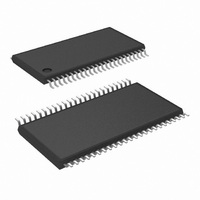
COP8CCR9IMT8/NOPB National Semiconductor, COP8CCR9IMT8/NOPB Datasheet - Page 16

COP8CCR9IMT8/NOPB
Manufacturer Part Number
COP8CCR9IMT8/NOPB
Description
IC MCU EEPROM 8BIT 32K 48-TSSOP
Manufacturer
National Semiconductor
Series
COP8™ 8Cr
Datasheet
1.COP8CDR9HVA8NOPB.pdf
(84 pages)
Specifications of COP8CCR9IMT8/NOPB
Core Processor
COP8
Core Size
8-Bit
Speed
20MHz
Connectivity
Microwire/Plus (SPI), UART/USART
Peripherals
Brown-out Detect/Reset, POR, PWM, WDT
Number Of I /o
39
Program Memory Size
32KB (32K x 8)
Program Memory Type
FLASH
Ram Size
1K x 8
Voltage - Supply (vcc/vdd)
2.7 V ~ 5.5 V
Data Converters
A/D 16x10b
Oscillator Type
Internal
Operating Temperature
-40°C ~ 85°C
Package / Case
48-TSSOP
Data Bus Width
8 bit
Maximum Clock Frequency
20 MHz
Data Ram Size
1 KB
On-chip Adc
10 bit, 16 channel
Number Of Programmable I/os
59
Number Of Timers
3
Height
0.9 mm
Interface Type
SPI, USART
Length
12.5 mm
Maximum Operating Temperature
+ 85 C
Minimum Operating Temperature
- 40 C
Supply Voltage (max)
5.5 V
Supply Voltage (min)
2.7 V
Width
6.1 mm
Lead Free Status / RoHS Status
Lead free / RoHS Compliant
Eeprom Size
-
Lead Free Status / Rohs Status
Details
Other names
*COP8CCR9IMT8
*COP8CCR9IMT8/NOPB
COP8CCR9IMT8
*COP8CCR9IMT8/NOPB
COP8CCR9IMT8
www.national.com
Output Current Levels
D Outputs
All Others
TRI-STATE Leakage
Allowable Sink Current per Pin
Maximum Input Current without Latchup (Note 5)
RAM Retention Voltage, V
Input Capacitance
Load Capacitance on D2
Voltage on G6 to Force Execution from Boot
ROM(Note 8)
G6 Rise Time to Force Execution from Boot ROM
Input Current on G6 when Input
8.0 Electrical Characteristics
DC Electrical Characteristics (−40˚C ≤ T
Datasheet min/max specification limits are guaranteed by design, test, or statistical analysis.
AC Electrical Characteristics (−40˚C ≤ T
Instruction Cycle Time (t
Output Propagation Delay
Frequency of MICROWIRE/PLUS in
Slave Mode
MICROWIRE/PLUS Setup Time (t
MICROWIRE/PLUS Hold Time (t
MICROWIRE/PLUS Output Propagation
Delay (t
Input Pulse Width
Output Pulse Width
USART Bit Time when using External
CKX
USART CKX Frequency when being
Driven by Internal Baud Rate Generator
Reset Pulse Width
t
Note 10: Maximum rate of voltage change must be
Source
Sink (Note 7)
Source (Weak Pull-Up Mode)
Source (Push-Pull Mode)
Sink (Push-Pull Mode) (Note 7)
C
Datasheet min/max specification limits are guaranteed by design, test, or statistical analysis.
Crystal/Resonator
Interrupt Input High Time
Interrupt Input Low Time
Timer 1 Input High Time
Timer 1 Input Low Time
Timer 2, 3 Input High Time (Note 6)
Timer 2, 3 Input Low Time (Note 6)
Timer 2, 3 Output High Time
Timer 2, 3 Output Low Time
= instruction cycle time.
UPD
)
Parameter
Parameter
C
R
)
(in HALT Mode)
>
UWH
V
UWS
CC
)
)
<
0.5 V/ms.
4.5V ≤ V
R
L
=2.2k, C
(Continued)
V
V
V
V
V
V
G6 rise time must be slower than
100 ns
V
CC
CC
CC
CC
CC
CC
IN
Conditions
= 11V, V
= 4.5V, V
= 4.5V, V
= 4.5V, V
= 4.5V, V
= 4.5V, V
= 5.5V
CC
L
≤ 5.5V
= 100 pF
Conditions
16
CC
OH
OL
OH
OH
OL
A
= 5.5V
A
= 1.0V
= 1.0V
= 3.8V
= 3.8V
= 3.8V
≤ +125˚C)
≤ +125˚C)
periods
6 CKI
Min
150
150
0.5
0.5
20
20
1
1
1
1
1
1
(Continued)
2 x V
−6.3
−6.3
Min
100
2.0
−9
−3
9
9
Typ
CC
Typ
500
Max
150
DC
2
2
V
±
1000
CC
Max
+3
200
1
7
+ 7
MCLK or t
MCLK or t
Units
MHz
MHz
µs
ns
ns
ns
ns
ns
t
t
t
t
t
Units
C
C
C
C
C
mA
mA
mA
mA
mA
mA
µA
µA
nS
µA
pF
pF
V
V
C
C


