AT89C5132-ROTIL Atmel, AT89C5132-ROTIL Datasheet - Page 148
AT89C5132-ROTIL
Manufacturer Part Number
AT89C5132-ROTIL
Description
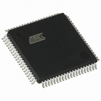
IC 8051 MCU FLASH 64K USB 80TQFP
Manufacturer
Atmel
Series
AT89C513xr
Datasheets
1.AT89C5132-ROTUL.pdf
(182 pages)
2.AT89C5132-ROTUL.pdf
(38 pages)
3.AT89C5132-ROTIL.pdf
(33 pages)
Specifications of AT89C5132-ROTIL
Core Processor
C52X2
Core Size
8-Bit
Speed
20MHz
Connectivity
IDE/ATAPI, I²C, MMC, PCM, SPI, UART/USART, USB
Peripherals
I²S, POR, WDT
Number Of I /o
44
Program Memory Size
64KB (64K x 8)
Program Memory Type
FLASH
Eeprom Size
4K x 8
Ram Size
2.25K x 8
Voltage - Supply (vcc/vdd)
2.7 V ~ 3.3 V
Data Converters
A/D 2x10b
Oscillator Type
Internal
Operating Temperature
-40°C ~ 85°C
Package / Case
80-TQFP, 80-VQFP
Lead Free Status / RoHS Status
Contains lead / RoHS non-compliant
Available stocks
Company
Part Number
Manufacturer
Quantity
Price


21.1.1
21.1.2
21.1.3
148
AT89C5132
Clock Generator
Channel Selection
Conversion Precision
Figure 21-2. Timing Diagram
The ADC clock is generated by division of the peripheral clock (see details in Section “X2 Fea-
ture”, page 12). The division factor is then given by ADCP4:0 bits in ADCLK register. Figure 21-
3 shows the ADC clock generator and its calculation formula
Figure 21-3. ADC Clock Generator and Symbol Caution:
Note:
The channel on which conversion is performed is selected by the ADCS bit in ADCON register
according to Table 30.
Table 30. ADC Channel Selection
The 10-bit precision conversion is achieved by stopping the CPU core activity during conversion
for limiting the digital noise induced by the core. This mode called the Pseudo-Idle mode
enabled by setting the ADIDL bit in ADCON register
Section "Conversion Launching", page 149), the CPU core is stopped until the end of the con-
1. In all cases, the ADC clock frequency may be higher than the maximum F
2. The ADCD value of 0 is equivalent to an ADCD value of 32.
ADEOC
ADSST
CLOCK
ADEN
reported in the Section “Analog to Digital Converter”, page 201.
PER
CLK
ADCS
T
0
1
÷ 2
SETUP
T
ADCD4:0
ADCLK
ADCLK
ADCclk
=
(3)
-------------------------
2 ADCD
PERclk
⋅
. Thus, when conversion is launched (see
T
ADC Clock
CONV
(1)
.
Channel
AIN1
AIN0
ADC Clock Symbol
CLOCK
ADCLK
ADC
4173E–USB–09/07
parameter
(1),(2)
is
Related parts for AT89C5132-ROTIL
Image
Part Number
Description
Manufacturer
Datasheet
Request
R

Part Number:
Description:
Manufacturer:
Atmel Corporation
Datasheet:

Part Number:
Description:
MCU 8051 FLASH USB 80TQFP
Manufacturer:
Atmel
Datasheet:

Part Number:
Description:
DEV KIT FOR AVR/AVR32
Manufacturer:
Atmel
Datasheet:
Part Number:
Description:
INTERVAL AND WIPE/WASH WIPER CONTROL IC WITH DELAY
Manufacturer:
ATMEL Corporation
Datasheet:
Part Number:
Description:
Low-Voltage Voice-Switched IC for Hands-Free Operation
Manufacturer:
ATMEL Corporation
Datasheet:
Part Number:
Description:
MONOLITHIC INTEGRATED FEATUREPHONE CIRCUIT
Manufacturer:
ATMEL Corporation
Datasheet:
Part Number:
Description:
AM-FM Receiver IC U4255BM-M
Manufacturer:
ATMEL Corporation
Datasheet:
Part Number:
Description:
Monolithic Integrated Feature Phone Circuit
Manufacturer:
ATMEL Corporation
Datasheet:
Part Number:
Description:
Multistandard Video-IF and Quasi Parallel Sound Processing
Manufacturer:
ATMEL Corporation
Datasheet:
Part Number:
Description:
High-performance EE PLD
Manufacturer:
ATMEL Corporation
Datasheet:
Part Number:
Description:
8-bit Flash Microcontroller
Manufacturer:
ATMEL Corporation
Datasheet: