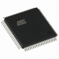
AT89C5132-ROTIL Atmel, AT89C5132-ROTIL Datasheet - Page 178

AT89C5132-ROTIL
Manufacturer Part Number
AT89C5132-ROTIL
Description
IC 8051 MCU FLASH 64K USB 80TQFP
Manufacturer
Atmel
Series
AT89C513xr
Datasheets
1.AT89C5132-ROTUL.pdf
(182 pages)
2.AT89C5132-ROTUL.pdf
(38 pages)
3.AT89C5132-ROTIL.pdf
(33 pages)
Specifications of AT89C5132-ROTIL
Core Processor
C52X2
Core Size
8-Bit
Speed
20MHz
Connectivity
IDE/ATAPI, I²C, MMC, PCM, SPI, UART/USART, USB
Peripherals
I²S, POR, WDT
Number Of I /o
44
Program Memory Size
64KB (64K x 8)
Program Memory Type
FLASH
Eeprom Size
4K x 8
Ram Size
2.25K x 8
Voltage - Supply (vcc/vdd)
2.7 V ~ 3.3 V
Data Converters
A/D 2x10b
Oscillator Type
Internal
Operating Temperature
-40°C ~ 85°C
Package / Case
80-TQFP, 80-VQFP
Lead Free Status / RoHS Status
Contains lead / RoHS non-compliant
Available stocks
Company
Part Number
Manufacturer
Quantity
Price
i
AT89C5132
1
2
3
4
5
6
7
8
9
10 Interrupt System .................................................................................... 34
11 Power Management ............................................................................... 44
Description ............................................................................................... 1
Typical Applications ................................................................................ 1
Block Diagram .......................................................................................... 2
Pin Description ......................................................................................... 3
Address Spaces ..................................................................................... 11
Clock Controller ..................................................................................... 12
Program/Code Memory ......................................................................... 17
Data Memory .......................................................................................... 22
Special Function Registers ................................................................... 29
4.1 Signals ......................................................................................................................4
4.2 Internal Pin Structure ..............................................................................................10
6.1 Oscillator ................................................................................................................12
6.2 X2 Feature ..............................................................................................................12
6.3 PLL .........................................................................................................................13
6.4 Registers ................................................................................................................14
7.1 Flash Memory Architecture ....................................................................................17
7.2 Hardware Security System .....................................................................................18
7.3 Boot Memory Execution .........................................................................................19
7.4 Registers ................................................................................................................20
7.5 Hardware Bytes ......................................................................................................20
8.1 Internal Space ........................................................................................................22
8.2 External Space .......................................................................................................23
8.3 Dual Data Pointer ...................................................................................................26
8.4 Registers ................................................................................................................27
10.1 Interrupt System Priorities ....................................................................................34
10.2 External Interrupts ................................................................................................37
10.3 Registers ..............................................................................................................38
11.1 Reset ....................................................................................................................44
11.2 Reset Recommendation to Prevent Flash Corruption ..........................................45
11.3 Idle Mode ..............................................................................................................46
11.4 Power-down Mode ...............................................................................................46
4173E–USB–09/07


