AT89C5132-ROTIL Atmel, AT89C5132-ROTIL Datasheet - Page 82
AT89C5132-ROTIL
Manufacturer Part Number
AT89C5132-ROTIL
Description
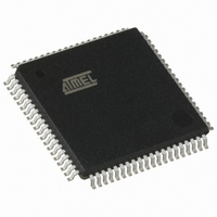
IC 8051 MCU FLASH 64K USB 80TQFP
Manufacturer
Atmel
Series
AT89C513xr
Datasheets
1.AT89C5132-ROTUL.pdf
(182 pages)
2.AT89C5132-ROTUL.pdf
(38 pages)
3.AT89C5132-ROTIL.pdf
(33 pages)
Specifications of AT89C5132-ROTIL
Core Processor
C52X2
Core Size
8-Bit
Speed
20MHz
Connectivity
IDE/ATAPI, I²C, MMC, PCM, SPI, UART/USART, USB
Peripherals
I²S, POR, WDT
Number Of I /o
44
Program Memory Size
64KB (64K x 8)
Program Memory Type
FLASH
Eeprom Size
4K x 8
Ram Size
2.25K x 8
Voltage - Supply (vcc/vdd)
2.7 V ~ 3.3 V
Data Converters
A/D 2x10b
Oscillator Type
Internal
Operating Temperature
-40°C ~ 85°C
Package / Case
80-TQFP, 80-VQFP
Lead Free Status / RoHS Status
Contains lead / RoHS non-compliant
Available stocks
Company
Part Number
Manufacturer
Quantity
Price


16. MultiMedia Card Controller
16.1
16.1.1
16.1.2
16.2
82
Card Concept
Bus Concept
AT89C5132
Card Signals
Card Registers
The AT89C5132 implements a MultiMedia Card (MMC) controller. The MMC is used to store
files in removable Flash memory cards that can be easily plugged or removed from the
application.
The basic MultiMedia Card concept is based on transferring data via a minimal number of
signals.
The communication signals are:
•
•
•
Within the card interface five registers are defined: OCR, CID, CSD, RCA and DSR. These can
be accessed only by corresponding commands.
The 32-bit Operation Conditions Register (OCR) stores the V
register is optional and can be read only.
The 128-bit wide CID register carries the card identification information (Card ID) used during
the card identification procedure.
The 128-bit wide Card-Specific Data register (CSD) provides information on how to access the
card contents. The CSD defines the data format, error correction type, maximum data access
time, data transfer speed, and whether the DSR register can be used.
The 16-bit Relative Card Address register (RCA) carries the card address assigned by the host
during the card identification. This address is used for the addressed host-card communication
after the card identification procedure
The 16-bit Driver Stage Register (DSR) can be optionally used to improve the bus performance
for extended operating conditions (depending on parameters like bus length, transfer rate or
number of cards).
The MultiMedia Card bus is designed to connect either solid-state mass-storage memory or I/O-
devices in a card format to multimedia applications. The bus implementation allows the cover-
age of application fields from low-cost systems to systems with a fast data transfer rate. It is a
single master bus with a variable number of slaves. The MultiMedia Card bus master is the bus
controller and each slave is either a single mass storage card (with possibly different technolo-
gies such as ROM, OTP, Flash etc.) or an I/O-card with its own controlling unit (on card) to
perform the data transfer.
The MultiMedia Card bus also includes power connections to supply the cards.
CLK: with each cycle of this signal an one bit transfer on the command and data lines is
done. The frequency may vary from zero to the maximum clock frequency.
CMD: is a bidirectional command channel used for card initialization and data transfer
commands. The CMD signal has two operation modes: open-drain for initialization mode
and push-pull for fast command transfer. Commands are sent from the MultiMedia Card bus
master to the card and responses from the cards to the host.
DAT: is a bidirectional data channel. The DAT signal operates in push-pull mode. Only one
card or the host is driving this signal at a time.
DD
voltage profile of the card. The
4173E–USB–09/07
Related parts for AT89C5132-ROTIL
Image
Part Number
Description
Manufacturer
Datasheet
Request
R

Part Number:
Description:
Manufacturer:
Atmel Corporation
Datasheet:

Part Number:
Description:
MCU 8051 FLASH USB 80TQFP
Manufacturer:
Atmel
Datasheet:

Part Number:
Description:
DEV KIT FOR AVR/AVR32
Manufacturer:
Atmel
Datasheet:
Part Number:
Description:
INTERVAL AND WIPE/WASH WIPER CONTROL IC WITH DELAY
Manufacturer:
ATMEL Corporation
Datasheet:
Part Number:
Description:
Low-Voltage Voice-Switched IC for Hands-Free Operation
Manufacturer:
ATMEL Corporation
Datasheet:
Part Number:
Description:
MONOLITHIC INTEGRATED FEATUREPHONE CIRCUIT
Manufacturer:
ATMEL Corporation
Datasheet:
Part Number:
Description:
AM-FM Receiver IC U4255BM-M
Manufacturer:
ATMEL Corporation
Datasheet:
Part Number:
Description:
Monolithic Integrated Feature Phone Circuit
Manufacturer:
ATMEL Corporation
Datasheet:
Part Number:
Description:
Multistandard Video-IF and Quasi Parallel Sound Processing
Manufacturer:
ATMEL Corporation
Datasheet:
Part Number:
Description:
High-performance EE PLD
Manufacturer:
ATMEL Corporation
Datasheet:
Part Number:
Description:
8-bit Flash Microcontroller
Manufacturer:
ATMEL Corporation
Datasheet: