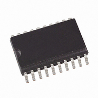
ATAM893T-TKS Atmel, ATAM893T-TKS Datasheet - Page 7

ATAM893T-TKS
Manufacturer Part Number
ATAM893T-TKS
Description
IC MON TIRE-PRESS ATARX9X SER
Manufacturer
Atmel
Series
MARC4r
Datasheet
1.ATAM893T-TKS.pdf
(98 pages)
Specifications of ATAM893T-TKS
Core Processor
MARC4
Core Size
4-Bit
Speed
4MHz
Connectivity
SSI (2-Wire, 3 Wire)
Peripherals
Brown-out Detect/Reset, POR, PWM, WDT
Number Of I /o
16
Program Memory Size
4KB (4K x 8)
Program Memory Type
EEPROM
Eeprom Size
64 x 16
Ram Size
256 x 4
Voltage - Supply (vcc/vdd)
1.8 V ~ 6.5 V
Oscillator Type
Internal
Operating Temperature
-40°C ~ 125°C
Package / Case
20-SOIC (5.3mm Width), 20-SO, 20-SOEIAJ
Lead Free Status / RoHS Status
Contains lead / RoHS non-compliant
Data Converters
-
4.2.3.2
4.2.3.3
4.2.3.4
4.2.3.5
4680C–4BMCU–01/05
RAM Address Registers
Expression Stack Pointer (SP)
Return Stack Pointer (RP)
RAM Address Registers (X and Y)
Figure 4-4.
The RAM is addressed with the four 8-bit wide RAM address registers: SP, RP, X and Y. These
registers allow access to any of the 256 RAM nibbles.
The stack pointer contains the address of the next-to-top 4-bit item (TOS-1) of the expression
stack. The pointer is automatically pre-incremented if a nibble is moved onto the stack or post-
decremented if a nibble is removed from the stack. Every post-decrement operation moves the
item (TOS-1) to the TOS register before the SP is decremented. After a reset the stack pointer
has to be initialized with “>SP S0” to allocate the start address of the expression stack area.
The return stack pointer points to the top element of the 12-bit wide return stack. The pointer
automatically pre-increments if an element is moved onto the stack, or it post-decrements if an
element is removed from the stack. The return stack pointer increments and decrements in
steps of 4. This means that every time a 12-bit element is stacked, a 4-bit RAM location is left
unwritten. This location is used by the qFORTH compiler to allocate 4-bit variables. After a reset
the return stack pointer has to be initialized via “>RP FCh”.
The X and Y registers are used to address any 4-bit item in the RAM. A fetch operation moves
the addressed nibble onto the TOS. A store operation moves the TOS to the addressed RAM
location. By using either the pre-increment or post-decrement addressing mode, arrays in the
RAM can be compared, filled or moved.
PC
Programming Model
11
RP
SP
X
Y
7
7
7
7
TOS
CCR
C
3
3
--
B
0
I
0
0
0
0
0
0
0
0
Interrupt enable
Branch
Reserved
Condition code register
Carry/borrow
Program counter
Return stack pointer
Expression stack pointer
RAM address register (X)
RAM address register (Y)
Top of stack register
ATAM893-D
7


