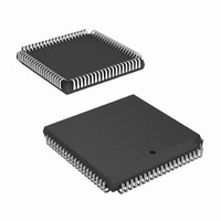
HSP50210JI-52Z Intersil, HSP50210JI-52Z Datasheet - Page 11

HSP50210JI-52Z
Manufacturer Part Number
HSP50210JI-52Z
Description
IC DEMODULATOR COSTAS 84-PLCC
Manufacturer
Intersil
Datasheet
1.HSP50210JC-52Z.pdf
(51 pages)
Specifications of HSP50210JI-52Z
Function
Demodulator
Frequency
52MHz
Rf Type
AM, FM
Package / Case
84-PLCC
Lead Free Status / RoHS Status
Lead free / RoHS Compliant
Available stocks
Company
Part Number
Manufacturer
Quantity
Price
Part Number:
HSP50210JI-52Z
Manufacturer:
INTERSIL
Quantity:
20 000
necessary insight to set the signal level into the Soft
Decision Slicer to yield optimum performance.
Note: Failure to consider the variations due to noise or
interfering signals, can result in signal limiting in the
HSP50210 processing algorithms, which will degrade the
system Bit Error Rate performance.
The AGC Loop is configured by the Power Detect Threshold
and AGC Loop Parameters Control Registers (see Tables 16
and 17 on page 33). Seven programmable parameters must be
set to configure the AGC Loop and its status outputs. Two
parameters, the Power Threshold and the AGC Threshold are
associated with the Error Detector and are represented in 8-bit
fractional unsigned binary format: 2
While the format provides a range from 0 to 1.9961 for the
thresholds, the Cartesian-to-Polar Converter scales the I
and Q input magnitudes by 0.81. Thus, if a full scale (±1)
complex (I and Q) input signal is presented to the converter,
the output will be √(0.81)
Threshold parameter value is the desired magnitude of the
signal as it enters the Soft Decision Slicer. It is the parameter
that will determine the error signal in the AGC loop. The
Power Threshold, on the other hand, determines only the
power threshold at which the THRESH signal is asserted. If
the signal magnitude exceeds the threshold, then the
THRESH is asserted. This may be used for signal detection,
power detection or external AGC around the A/D converter.
The AGC Threshold parameter is set in the AGC Loop
Parameters Control Register, Bits 16 through 23 (see
Table 17 on page 33). The Power Threshold parameter is
set in the Power Detect Threshold Control Register, Bits 0
through 7 (see Table 16 on page 33). Note that these two
threshold parameters are not required to be set to identical
or even related values, since they perform independent
functions.
The Enable AGC parameter sets the AGC Error Detector
output to zero if asserted and to normal error detection
output when not asserted. This control bit is set in the AGC
Loop Parameter Control Register, Bit 31 (see Tables 17 on
page 33). This bit is used to disable the AGC loop.
The remaining AGC parameters determine the AGC loop
characteristics: gain tracking, tracking rate and tracking limits.
The AGC Loop gain is set via two parameters: AGC Loop Gain
Exponent and AGC Loop Gain Mantissa. In general, the higher
the loop gain, the faster signal level acquisition and tracking,
but this must be tempered by the specific signal characteristics
of the application and the remaining programmable loop
parameters. For the HSP50210, the AGC Loop Gain provides
for a variable attenuation of the input to the loop filter. The AGC
gain mantissa is a 4-bit value which provides error signal
scaling from 0.000 to 0.9375, with a resolution of 0.0625.
Table 2 on page 11 details the discrete set of decimal values
possible for the AGC Loop Gain mantissa. The exponent
provides a shift factor scaling from 2
page 11 details the discrete set of decimal values possible for
2
+ (0.81)
11
0
2
-7
2
-1
= 1.1455. The AGC
to 2
2
-2
-14
2
-3
. Table 3 on
2
-4
2
-5
2
-6
2
-7
.
HSP50210
the AGC Loop Gain Exponent. When combined, the exponent
and mantissa provide a loop gain defined as Equation 7:
AGC Loop Gain: G
where M is a binary number with a range from 0 to 15 and E
is a 3-bit binary value from 0 to 7. M and E are the
parameters set in the AGC Loop Parameters Control
Register, Bits 24 through 30 (see Table 17 on page 33). The
composite range of the AGC loop Gain is 0.0000 to
[0.9375][2 to 7]. This will scale the AGC error signal to a
range of 0.000 to (1.1455)(0.9375)(2 to 7) = 1.07297(2 to 7).
BINARY CODE
TABLE 2. AGC LOOP GAIN BINARY MANTISSA TO DECIMAL
TABLE 3. AGC LOOP BINARY EXPONENT TO SCALED
(MMMM)
BINARY
CODE
0000
0001
0010
0011
0100
0101
0110
0111
(EEE)
000
001
010
011
100
101
110
111
SCALED MANTISSA MAPPING
DECIMAL EXPONENT MAPPING
AGC
MANTISSA
DECIMAL
SCALED
0.0000
0.0625
0.1250
0.1875
0.2500
0.3125
0.3750
0.4375
DECIMAL/HEX
=
EXPONENT
[
( ) 2
M
0
1
2
3
4
5
6
7
(
–
4
)
] 2
(MMMM)
BINARY
[
CODE
(
1000
1001
1010
1011
1100
1101
1110
1111
–
(
7
+
DECIMAL SCALED
E
)
)
EXPONENT
]
MANTISSA
2
2
2
2
2
DECIMAL
2
2
2
SCALED
-10
-12
-13
-14
-11
-7
-8
-9
0.5000
0.5625
0.6250
0.6875
0.7500
0.8125
0.8750
0.9375
July 2, 2008
FN3652.5
(EQ. 7)


