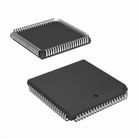
HSP50210JI-52Z Intersil, HSP50210JI-52Z Datasheet - Page 36

HSP50210JI-52Z
Manufacturer Part Number
HSP50210JI-52Z
Description
IC DEMODULATOR COSTAS 84-PLCC
Manufacturer
Intersil
Datasheet
1.HSP50210JC-52Z.pdf
(51 pages)
Specifications of HSP50210JI-52Z
Function
Demodulator
Frequency
52MHz
Rf Type
AM, FM
Package / Case
84-PLCC
Lead Free Status / RoHS Status
Lead free / RoHS Compliant
Available stocks
Company
Part Number
Manufacturer
Quantity
Price
Part Number:
HSP50210JI-52Z
Manufacturer:
INTERSIL
Quantity:
20 000
POSITION
POSITION
POSITION
31-24
23-18
17-14
31-24
23-18
17-14
31-27
26-23
22-18
17-14
13-9
13-9
13-9
BIT
BIT
BIT
8-5
4-0
8-5
4-0
Not Used
Reserved
Carrier Lead Gain
Mantissa (Acquisition)
Carrier Lead Gain
Exponent (Acquisition)
Carrier Lag Gain
Mantissa (Acquisition)
Carrier Lag Gain
Exponent (Acquisition)
Not Used
Reserved
Carrier Lead Gain
Mantissa (Track)
Carrier Lead Gain
Exponent (Track)
Carrier Lag Gain
Mantissa (Track)
Carrier Lag Gain
Exponent (Track)
Reserved
Sweep Rate Mantissa
(Acquisition)
Sweep Rate Exponent
(Acquisition)
AFC Gain Mantissa
(Acquisition)
AFC Gain Exponent
(Acquisition)
FUNCTION
FUNCTION
FUNCTION
36
TABLE 25. CARRIER LOOP FILTER GAIN (ACQ) CONTROL REGISTER
TABLE 26. CARRIER LOOP FILTER GAIN (TRK
TABLE 27. FREQUENCY SWEEP/ AFC LOOP CONTROL REGISTER
No programming required.
Reserved. Set to 0 for proper operation.
These bits are the 4 fractional bits of the lead gain mantissa shown as follows.
Lead Gain Mantissa = 0 1. 2
This format provides a mantissa range from 1.0 to 1.9375 for mantissa settings from 0000 to 1111 Binary.
Bit position 17 is the MSB.
These bits set the lead gain exponent as given by:
Carrier Lead Gain Exponent = 2
where E corresponds to the 5-bit binary value programmed here. Thus, a gain range from
2
Binary. Bit position 13 is the MSB.
Format same as lead gain mantissa. Bit position 8 is the MSB.
Format same as lead gain exponent. Bit position 4 is the MSB.
No Programming required.
Reserved. Set to 0 for proper operation.
Format same as lead gain mantissa (see Table 25). Bit position 17 is the MSB.
Format same as lead gain exponent (see Table 25). Bit position 13 is the MSB.
Format same as lead gain mantissa (see Table 25). Bit position 8 is the MSB.
Format same as lead gain exponent (see Table 25). Bit position 4 is the MSB.
Reserved. Set to 0 for proper operation.
Sets carrier track sweep rate used during acquisition (see “Frequency Sweep Block” on page 23). Format
same as lead gain mantissa (see Table 25). Bit position 22 is the MSB.
Sets carrier track sweep rate used during acquisition (see “Frequency Sweep Block” on page 23). Format
same as lead gain exponent (see Table 25). Bit position 22 is the MSB. M = 0000,
E = 00000 is 2
Sets Frequency Error Gain. Format same as lead gain mantissa (see Table 25). Bit position 11 is the
MSB.
Sets Frequency Error Gain. Format same as lead gain exponent (see Table 25). Bit position 4 is the MSB.
-1
to 2
-32
(relative to the MSB position of the NCO control word) may be achieved for E = 11111 to 00000
-28
DESTINATION ADDRESS = 10
DESTINATION ADDRESS = 11
DESTINATION ADDRESS = 12
.
HSP50210
-1
2
-2
-(32-E).
2
-3
2
-4.
DESCRIPTION
)
DESCRIPTION
DESCRIPTION
CONTROL REGISTER
July 2, 2008
FN3652.5


