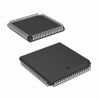
HSP50210JI-52Z Intersil, HSP50210JI-52Z Datasheet - Page 31

HSP50210JI-52Z
Manufacturer Part Number
HSP50210JI-52Z
Description
IC DEMODULATOR COSTAS 84-PLCC
Manufacturer
Intersil
Datasheet
1.HSP50210JC-52Z.pdf
(51 pages)
Specifications of HSP50210JI-52Z
Function
Demodulator
Frequency
52MHz
Rf Type
AM, FM
Package / Case
84-PLCC
Lead Free Status / RoHS Status
Lead free / RoHS Compliant
Available stocks
Company
Part Number
Manufacturer
Quantity
Price
Part Number:
HSP50210JI-52Z
Manufacturer:
INTERSIL
Quantity:
20 000
NOTE: These processor signals are meant to be representative. The actual shape of the waveforms will be set by the microprocessor used. Verify
that the processor waveforms meet the parameters in “Waveforms” on page 50 to ensure proper operation. The Processor waveforms are not
required to be synchronous to CLK. They are shown that way to clarify the illustration.
10. Load Write Address Register with 25
.
1. LKINT Asserts Indicating End of Lock Detector Accumulation Cycle; Accumulators Ready to Read.
2. Set A0-2 to 5 for Reading Lock Detector.
3. Load Read Address Register with 3
4. Set A0-2 to 3 for Phase Error (PE) Read.
5. Assert RD and read (Phase Error (PE) MSW; PE LSW; False Lock (FL) MSW; FL LSW).
6. Change Read Address to (2; 1; 0) to read various Lock Detection values.
7. Change Address to 4 to Initialize the Lock Detector.
8. Load Write Address Register with 30
9. Keep Address to 4 to Restart the Lock Detector.
an effect in µP mode).
LKINT
SR-7
A0-2
C0-7
CLK
WR
RD
1
2
5
31
3
3
FIGURE 24. PROCESSOR INTERRUPT MONITOR/LOCK DETECTOR READ
A0-2
C7-0
4
CLK
RD
dec
dec
dec
FIGURE 25. INTERNAL STATUS REGISTER READ
to enable the Lock Detector Phase Error Accumulator for Reading.
5
3
to initialize the Lock Detector Accumulators and Reset Integration Counters. (Only has
to restart the Lock Detector. (Only necessary if not in the µP mode).
PE
STATUS CAN CHANGE EVERY CLK
MSW
6
4
HSP50210
2
5
PE
LSW
6
1
5
FL
MSW
6
0
5
FL
LSW
7
30
8
4
9
25
10
4
July 2, 2008
FN3652.5


