NS16C2752TVSX/NOPB National Semiconductor, NS16C2752TVSX/NOPB Datasheet - Page 13

NS16C2752TVSX/NOPB
Manufacturer Part Number
NS16C2752TVSX/NOPB
Description
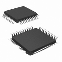
IC UART DUAL 64BYTE 48-TQFP
Manufacturer
National Semiconductor
Datasheet
1.NS16C2552TVSXNOPB.pdf
(44 pages)
Specifications of NS16C2752TVSX/NOPB
Features
Programmable
Number Of Channels
2, DUART
Fifo's
64 Byte
Voltage - Supply
2.97 V ~ 5.5 V
With Auto Flow Control
Yes
With Irda Encoder/decoder
Yes
With Modem Control
Yes
Mounting Type
Surface Mount
Package / Case
48-VFQFP
Lead Free Status / RoHS Status
Lead free / RoHS Compliant
Available stocks
Company
Part Number
Manufacturer
Quantity
Price
Company:
Part Number:
NS16C2752TVSX/NOPB
Manufacturer:
Texas Instruments
Quantity:
10 000
LSR
Rx Trigger
RXRDY Timer Time-out in 4-word time plus 12-bit delay time.
TXRDY
MSR
Xoff or Special
character
CTS
RTS
Generation
6.5 FIFO CONTROL REGISTER (FCR)
This is a write only register at the same location as the IIR (the
IIR is a read only register). This register is used to enable the
Interrupt
Priority
7:6
3:1
Bit
Level
5
4
0
1
2
3
4
5
6
7
-
INT Src 3:1
FIFOs Ena
Bit Name
INT Src 5
INT Src 4
INT Src 0
Any bit is set in LSR[4:1] (Break Interrupt, Framing, Rx
parity, or overrun error).
Rx FIFO reached trigger level.
THR empty.
Any state change in MSR[3:0].
Detection of Xoff or Special character.
Input pin toggles from logic 0 to 1 during CTS auto flow
control mode.
Output pin toggles from logic 0 to 1 during RTS auto
flow control mode.
5
0
0
0
0
0
0
1
0
4
0
0
0
0
0
1
0
0
IIR Register Status Bits
Interrupt Sources
R/W
Def
000
00
R
R
R
R
R
0
0
1
3
0
1
0
0
0
0
0
0
TABLE 7. Interrupt Source and Priority Level
FIFO Enable Status (FCR 0x2.0)
2'b11 = Tx and Rx FIFOs enabled.
2'b00 = Tx and Rx FIFOs disabled (default).
RTS/CTS Interrupt Status
1 = RTS or CTS changed state from low to high.
0 = No change on RTS or CTS from low to high (default).
Xoff or Special Character Interrupt Status
1 = Receiver detected Xoff or special character.
0 = No Xoff character match (default).
Interrupt Source Status
These three bits indicates the source of a pending interrupt. Refer to Table 7 for interrupt
source and priority.
Interrupt Status
1 = No interrupt is pending (default).
0 = An interrupt is pending and the IIR content may be used as a pointer for the interrupt
service routine.
TABLE 8. Interrupt Sources and Clearing
2
1
1
1
0
0
0
0
0
TABLE 6. IIR (0x2)
1
1
0
0
1
0
0
0
0
13
0
0
0
0
0
0
0
0
1
FIFOs, clear the FIFOs, set the FIFO trigger level, and select
the DMA mode.
Read LSR register. (Interrupt flags and tags are not cleared
until the character(s) that generated the interrupt(s) has/have
been emptied or cleared.)
Read FIFO data until FIFO pointer falls below the trigger level.
Read RBR.
Read from IIR register or a write to THR.
Read from MSR register.
Read from IIR register or reception of Xon character (or
reception of next character if interrupt is caused by Special
character).
Read from IIR or MSR.
Read from IIR or MSR.
LSR
RXRDY (Receive data time-out)
RXRDY (Receive data ready)
TXRDY (Transmit data ready)
MSR (Modem Status Register)
RXRDY (Received Xoff or special character)
CTS, RTS change state from low to high
None (default)
Description
Interrupt Clearing
Interrupt Source
www.national.com


