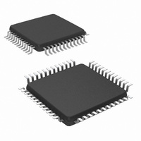
NS16C2752TVSX/NOPB National Semiconductor, NS16C2752TVSX/NOPB Datasheet - Page 14

NS16C2752TVSX/NOPB
Manufacturer Part Number
NS16C2752TVSX/NOPB
Description
IC UART DUAL 64BYTE 48-TQFP
Manufacturer
National Semiconductor
Datasheet
1.NS16C2552TVSXNOPB.pdf
(44 pages)
Specifications of NS16C2752TVSX/NOPB
Features
Programmable
Number Of Channels
2, DUART
Fifo's
64 Byte
Voltage - Supply
2.97 V ~ 5.5 V
With Auto Flow Control
Yes
With Irda Encoder/decoder
Yes
With Modem Control
Yes
Mounting Type
Surface Mount
Package / Case
48-VFQFP
Lead Free Status / RoHS Status
Lead free / RoHS Compliant
Available stocks
Company
Part Number
Manufacturer
Quantity
Price
Company:
Part Number:
NS16C2752TVSX/NOPB
Manufacturer:
Texas Instruments
Quantity:
10 000
www.national.com
Bit
7:6
5:4
Mode 0: Mode 0 allows for single transfer in each DMA cycle.
When in the 16450 Mode (FCR[0] = 0) or in the FIFO Mode
(FCR[0] = 1, FCR[3] = 0) and there is at least one character
in the RCVR FIFO or RCVR Buffer Register, the RXRDY pin
will go active low. After going active, the RXRDY pin will be
inactive when there is no character in the FIFO or Buffer Reg-
ister.
On The Tx side, TXRDY is active low when XMIT FIFO or
XMIT Holding Register is empty. TXRDY returns to high when
XMIT FIFO or XMIT holding register is not empty.
Mode 1: Mode 1 allows for multiple transfer or multi-character
burst transfer. In the FIFO Mode (FCR[0] = 1, FCR[3] = 1)
3
2
Bit Name
Trig Level
Rx FIFO
Tx FIFO
Tx FIFO
Select
Select
Reset
Mode
DMA
Trig
Sel
R/W
Def
00
00
W
W
W
W
0
0
Rx FIFO Trigger Select
FCR[6] and FCR[7] are used to designate the interrupt trigger level. When the number of characters in
the RCVR FIFO equals the designated interrupt trigger level, a Received Data Available Interrupt is
activated. This interrupt must be enabled by IER[0]=1.
For NS16C2552 with 16-byte FIFO:
For NS16C2752 with 64-byte FIFO:
Refer to Section 7.5 SOFTWARE XON/XOFF FLOW CONTROL and Section 7.9 DMA OPERATION for
software flow control using FIFO trigger level.
Transmit FIFO Trigger Level Selection
The transmit FIFO trigger threshold selection is only available in NS16C2752. When enabled, a transmit
interrupt is generated and TXRDY is asserted when the number of empty spaces in the FIFO exceeds
the threshold level.
For NS16C2752 with 64-byte FIFO:
Refer to Section 7.4 TRANSMIT OPERATION and Section 7.9 DMA OPERATION for transmit FIFO
descriptions.
These two bits are reserved in NS16C2552 and have no impact when they are written to.
DMA Mode Select
This bit controls the RXRDY and TXRDY initiated DMA transfer mode.
1 = DMA Mode 1. Allows block transfers. Requires FCR 0x2.0=1 (FIFO mode).
0 = DMA Mode 0 (default). Single transfers.
Transmit FIFO Reset
This bit is only active when FCR bit 0 = 1.
1 = Reset XMIT FIFO pointers and all bytes in the XMIT FIFO (the Tx shift register is not cleared and is
cleared by MR reset). This bit has the self-clearing capability.
0 = No impact (default).
Note: Reset pointer will cause the characters in Tx FIFO to be lost.
FCR[7]
FCR[7]
FCR[5]
1
1
0
0
1
1
0
0
1
1
0
0
FCR[6]
FCR[6]
FCR[4]
1
0
1
0
1
0
1
0
1
0
1
0
TABLE 9. FCR (0x2)
Tx FIFO Trigger Level
Rx FIFO Trigger Level
Rx FIFO Trigger Level
= 14
= 8
= 4
= 1 (Default)
= 60
= 56
= 16
= 8 (Default)
= 56
= 32
= 16
= 8 (Default)
14
when the number of characters in the RCVR FIFO equals the
trigger threshold level or timeout occurs, the RXRDY goes
active low to initiate DMA transfer request. The RXRDY re-
turns high when RCVR FIFO becomes empty.
In the FIFO Mode (FCR[0] = 1, FCR[3] = 1) when there is (1)
no character in the XMIT FIFO for NS16C2552, or (2) empty
spaces exceed the threshold level for NS16C2752; the
TXRDY pin will go active low. This pin will become inactive
when the XMIT FIFO is completely full.
Description


