NS16C2752TVSX/NOPB National Semiconductor, NS16C2752TVSX/NOPB Datasheet - Page 30
NS16C2752TVSX/NOPB
Manufacturer Part Number
NS16C2752TVSX/NOPB
Description
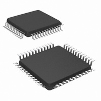
IC UART DUAL 64BYTE 48-TQFP
Manufacturer
National Semiconductor
Datasheet
1.NS16C2552TVSXNOPB.pdf
(44 pages)
Specifications of NS16C2752TVSX/NOPB
Features
Programmable
Number Of Channels
2, DUART
Fifo's
64 Byte
Voltage - Supply
2.97 V ~ 5.5 V
With Auto Flow Control
Yes
With Irda Encoder/decoder
Yes
With Modem Control
Yes
Mounting Type
Surface Mount
Package / Case
48-VFQFP
Lead Free Status / RoHS Status
Lead free / RoHS Compliant
Available stocks
Company
Part Number
Manufacturer
Quantity
Price
Company:

Part Number:
NS16C2752TVSX/NOPB
Manufacturer:
Texas Instruments
Quantity:
10 000


www.national.com
7.4.2 Transmit in non-FIFO Mode
Interrupt Mode
The THR empty flag LSR[5] is set when a data word is trans-
ferred to the TSR. THR flag can generate a transmit empty
interrupt IIR[1] enabled by IER[1]. The TSR flag LSR[6] is set
when TSR becomes empty. The host CPU may write one
character into the THR and wait for the next IIR[1] interrupt.
(Figure 10.)
DMA mode
In the DMA single transfer (mode 0), TXRDY asserts when
FIFO is empty initiating one DMA transfer and deasserts
when a character is written into the FIFO. (Figure 11.)
FIGURE 9. TXRDY in DMA Mode 1
FIGURE 10. Tx Non-FIFO Mode
20204812
20204811
30
7.4.3 Transmit Hardware Flow Control
CTS is a flow control input used to prevent remote receiver
FIFO data overflow. The CTS input is monitored to suspend/
resume the local transmitter. The automatic CTS flow control
can be enabled to suit specific application.
•
7.4.4 Transmit Flow Control Interrupt
•
•
An interrupt is generated when CTS pin is de-asserted (logic
1). IIR[5] is set to logic 1. The transmitter suspends transmis-
sion as soon as the stop bit is shifted out. Transmission is
resumed after the CTS pin is asserted logic 0, indicating re-
mote receiver is ready to accept data word.
7.5 SOFTWARE XON/XOFF FLOW CONTROL
Software flow control uses programmed Xon or Xoff charac-
ters to enable the transmit/receive flow control. The receiver
compares one or two sequentially received data words. If the
received character(s) match the programmed values, the
transmitter suspends operation as soon as the current trans-
mitting frame is completed. When a match occurs, the Xoff (if
enabled via IER[5]) flag is set and an interrupt is generated.
Following a transmission suspension, the UART monitors the
receive data stream for an Xon character. When a match is
found, the transmission resumes and the IIR[4] flag clears.
Upon reset, the Xon/Xoff characters are cleared to logic 0.
The user may write any Xon/Xoff value desired for software
flow control. Different conditions can be set to detect Xon/Xoff
characters and suspend/resume transmissions. When double
8-bit Xon/Xoff characters are selected, the UART compares
two consecutively received characters with two software flow
control 8-bit values (Xon1, Xon2, Xoff1, and Xoff2) and con-
trols transmission accordingly. Under the above described
flow control mechanisms, flow control characters are not
placed in the user accessible Rx data buffer or FIFO.
During the flow control operation, when Receive FIFO pointer
reaches the upper trigger level, the UART automatically trans-
mits Xoff1 and Xoff 2 messages via the serial TX line output
to the remote modem. When Receive FIFO pointer position
Enable auto CTS flow control EFR[7]=1.
Enable auto CTS flow control EFR[7]=1.
Enable CTS interrupt IER[7]=1.
FIGURE 11. TXRDY in DMA Mode 0
20204813
Related parts for NS16C2752TVSX/NOPB
Image
Part Number
Description
Manufacturer
Datasheet
Request
R

Part Number:
Description:
National Semiconductor [8-Bit D/A Converter]
Manufacturer:
National Semiconductor
Datasheet:
Part Number:
Description:
National Semiconductor [Media Coprocessor]
Manufacturer:
National Semiconductor
Datasheet:
Part Number:
Description:
Digitally Controlled Tone and Volume Circuit with Stereo Audio Power Amplifier, Microphone Preamp Stage and National 3D Sound
Manufacturer:
National Semiconductor
Datasheet:
Part Number:
Description:
Digitally Controlled Tone and Volume Circuit with Stereo Audio Power Amplifier, Microphone Preamp Stage and National 3D Sound
Manufacturer:
National Semiconductor
Datasheet:
Part Number:
Description:
AC97 Rev 2 Codec with Sample Rate Conversion and National 3D Sound
Manufacturer:
National Semiconductor
Part Number:
Description:
Manufacturer:
National Semiconductor
Datasheet:
Part Number:
Description:
Manufacturer:
National Semiconductor
Datasheet:
Part Number:
Description:
General Purpose, Low Voltage, Low Power, Rail-to-Rail Output Operational Amplifiers
Manufacturer:
National Semiconductor
Datasheet:
Part Number:
Description:
8-bit 20 MSPS flash A/D converter.
Manufacturer:
National Semiconductor
Datasheet:
Part Number:
Description:
Low Noise Quad Operational Amplifier
Manufacturer:
National Semiconductor
Datasheet:
Part Number:
Description:
Quad Differential Line Receivers
Manufacturer:
National Semiconductor
Datasheet:
Part Number:
Description:
Quad High Speed Trapezoidal? Bus Transceiver
Manufacturer:
National Semiconductor
Datasheet:
Part Number:
Description:
Dual Line Receiver
Manufacturer:
National Semiconductor
Datasheet:
Part Number:
Description:
TTL to 10k ECL Level Translator with Latch
Manufacturer:
National Semiconductor
Datasheet: