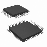
NS16C2752TVSX/NOPB National Semiconductor, NS16C2752TVSX/NOPB Datasheet - Page 16

NS16C2752TVSX/NOPB
Manufacturer Part Number
NS16C2752TVSX/NOPB
Description
IC UART DUAL 64BYTE 48-TQFP
Manufacturer
National Semiconductor
Datasheet
1.NS16C2552TVSXNOPB.pdf
(44 pages)
Specifications of NS16C2752TVSX/NOPB
Features
Programmable
Number Of Channels
2, DUART
Fifo's
64 Byte
Voltage - Supply
2.97 V ~ 5.5 V
With Auto Flow Control
Yes
With Irda Encoder/decoder
Yes
With Modem Control
Yes
Mounting Type
Surface Mount
Package / Case
48-VFQFP
Lead Free Status / RoHS Status
Lead free / RoHS Compliant
Available stocks
Company
Part Number
Manufacturer
Quantity
Price
Company:
Part Number:
NS16C2752TVSX/NOPB
Manufacturer:
Texas Instruments
Quantity:
10 000
www.national.com
6.6 LINE CONTROL REGISTER (LCR)
The system programmer specifies the format of the asyn-
chronous data communications exchange and sets the Divi-
Bit
7
6
5
4
3
2
Tx/Rx Stop-bit
Tx Break Ena
Divisor Latch
Tx/Rx Parity
Length Sel
Even/Odd
Bit Name
Parity Sel
Parity Sel
Default
Forced
Ena
Ena
R/W
R/W
R/W
R/W
R/W
R/W
R/W
Def
0
0
0
0
0
0
Divisor Latch Access Bit (DLAB)
This bit must be set (logic 1) to access the Divisor Latches of the Baud Generator and the Alternate
Function Register during a read or write operation. It must be cleared (logic 0) to access any other
register.
1 = Enable access to the Divisor Latches of the Baud Generator and the AFR.
0 = Enable access to other registers (default).
Set Tx Break Enable
This bit is the Break Control bit. It causes a break condition to be transmitted to the receiving
UART. The Break Control bit acts only on SOUT and has no effect on the transmitter logic.
1 = Serial output (SOUT) is forced to the Spacing State (break state, logic 0).
0 = The break transmission is disabled (default).
Note: This feature enables the CPU to alert a terminal in a computer communication system. If
the following sequence is followed, no erroneous or extraneous character will be transmitted
because of the break.
1. Load an all 0s, pad character, in response to THRE.
2. Set break after the next THRE.
3. Wait for the transmitter to be idle, (Transmitter Empty TEMT = 1), and clear break when normal
transmission has to be restored.
During the break, the transmitter can be used as a character timer to establish the break duration.
During the break state, any word left in THR will be shifted out of the register but blocked by SOUT
as forced to break state. This word will be lost.
Tx and Rx Forced Parity Select
When parity is enabled, this bit selects the forced parity format.
Tx and Rx Even/Odd Parity Select
This bit is only effective when LCR[3]=1. This bit selects even or odd parity format.
1 = Odd parity is transmitted or checked.
0 = Even parity is transmitted or checked (default).
Tx and Rx Parity Enable
This bit enables parity generation.
1 = A parity is generated during the data transmission. The receiver checks for parity error of the
data received.
0 = No parity (default).
Tx and Rx Stop-bit Length Select
This bit specifies the number of Stop bits transmitted with each serial character.
Stop-bit length is measured in bit time.
LCR[5]
LCR[2]
1
1
0
0
X
1
1
0
LCR[4]
Word Length Sel
1
0
1
0
X
TABLE 10. LCR (0x3)
6,7,8
5
5,6,7,8
LCR[3]
16
1
1
1
1
0
sor Latch Access bit via the Line Control Register (LCR). This
is a read and write register.
Stop-bit Length
Force parity to space = 0
Force parity to mark = 1
Even parity
Odd parity
No parity
Parity Select
Description
= 2
= 1.5
= 1(Default)


