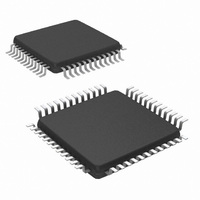
NS16C2752TVSX/NOPB National Semiconductor, NS16C2752TVSX/NOPB Datasheet - Page 3

NS16C2752TVSX/NOPB
Manufacturer Part Number
NS16C2752TVSX/NOPB
Description
IC UART DUAL 64BYTE 48-TQFP
Manufacturer
National Semiconductor
Datasheet
1.NS16C2552TVSXNOPB.pdf
(44 pages)
Specifications of NS16C2752TVSX/NOPB
Features
Programmable
Number Of Channels
2, DUART
Fifo's
64 Byte
Voltage - Supply
2.97 V ~ 5.5 V
With Auto Flow Control
Yes
With Irda Encoder/decoder
Yes
With Modem Control
Yes
Mounting Type
Surface Mount
Package / Case
48-VFQFP
Lead Free Status / RoHS Status
Lead free / RoHS Compliant
Available stocks
Company
Part Number
Manufacturer
Quantity
Price
Company:
Part Number:
NS16C2752TVSX/NOPB
Manufacturer:
Texas Instruments
Quantity:
10 000
12.0 Physical Dimensions .................................................................................................................... 43
List of Figures
FIGURE 1. Internal Clock Dividers ............................................................................................................... 18
FIGURE 2. Crystal Oscillator Circuitry .......................................................................................................... 26
FIGURE 3. Clock Input Circuitry .................................................................................................................. 27
FIGURE 4. Rx FIFO Mode ........................................................................................................................ 27
FIGURE 5. RXRDY in DMA Mode 1 ............................................................................................................. 28
FIGURE 6. Rx Non-FIFO Mode .................................................................................................................. 28
FIGURE 7. RXRDY in DMA Mode 0 ............................................................................................................. 28
FIGURE 8. Tx FIFO Mode ......................................................................................................................... 29
FIGURE 9. TXRDY in DMA Mode 1 ............................................................................................................. 30
FIGURE 10. Tx Non-FIFO Mode ................................................................................................................. 30
FIGURE 11. TXRDY in DMA Mode 0 ............................................................................................................ 30
FIGURE 12. IrDA Data Transmission ........................................................................................................... 32
FIGURE 13. Internal Loopback Functional Diagram ......................................................................................... 33
FIGURE 14. Nominal Mid-bit Sampling ......................................................................................................... 34
FIGURE 15. Deviated Baud Rate Sampling .................................................................................................... 34
FIGURE 16. Crystal Oscillator Circuit ........................................................................................................... 35
FIGURE 17. External Clock Input ................................................................................................................ 39
FIGURE 18. Modem Control Timing ............................................................................................................. 39
FIGURE 19. Host Interface Read Timing ....................................................................................................... 39
FIGURE 20. Host Interface Write Timing ....................................................................................................... 40
FIGURE 21. Receiver Timing ..................................................................................................................... 40
FIGURE 22. Receiver Timing Non-FIFO Mode ................................................................................................ 40
FIGURE 23. Receiver Timing FIFO Mode ...................................................................................................... 41
FIGURE 24. Transmitter Timing .................................................................................................................. 41
FIGURE 25. Transmitter Timing Non-FIFO Mode ............................................................................................. 41
FIGURE 26. Transmitter Timing FIFO Mode ................................................................................................... 42
List of Tables
TABLE 1. Basic Register Addresses ............................................................................................................. 9
TABLE 2. NS16C2552 Register Summary ..................................................................................................... 10
TABLE 3. RBR (0x0) ............................................................................................................................... 11
TABLE 4. THR (0x0) ............................................................................................................................... 12
TABLE 5. IER (0x1) ................................................................................................................................. 12
TABLE 6. IIR (0x2) .................................................................................................................................. 13
TABLE 7. Interrupt Source and Priority Level .................................................................................................. 13
TABLE 8. Interrupt Sources and Clearing ...................................................................................................... 13
TABLE 9. FCR (0x2) ............................................................................................................................... 14
TABLE 10. LCR (0x3) .............................................................................................................................. 16
TABLE 11. MCR (0x4) ............................................................................................................................. 18
TABLE 12. LSR (0x5) .............................................................................................................................. 20
TABLE 13. MSR (0x6) ............................................................................................................................. 22
TABLE 14. SCR (0x7) .............................................................................................................................. 23
TABLE 15. DLL (0x0, LCR[7] = 1, LCR != 0xBF) .............................................................................................. 23
TABLE 16. DLM (0x1, LCR[7] = 1, LCR != 0xBF) ............................................................................................. 23
TABLE 17. Baud Rate Generation Using 1.8432 MHz Clock with MCR[7]=0
........................................................... 23
TABLE 18. AFR (0x2, LCR[7] = 1, LCR != 0xBF) ............................................................................................. 24
TABLE 19. DREV (0x0, LCR[7]=1, LCR!=0xBF, DLL=DLM=0x00) ........................................................................ 24
TABLE 20. EFR (0x2, LCR = 0xBF) ............................................................................................................. 25
TABLE 21. Xon1 (0x4, LCR=0xBF) .............................................................................................................. 26
TABLE 22. Xon2 (0x5, LCR=0xBF) .............................................................................................................. 26
TABLE 23. Xoff1 (0x6, LCR=0xBF) .............................................................................................................. 26
TABLE 24. Xoff2 (0x7, LCR=0xBF) .............................................................................................................. 26
TABLE 25. Crystal Component Requirement .................................................................................................. 26
TABLE 26. Output State After Reset ............................................................................................................ 27
TABLE 27. Auto-RTS HW Flow Control on NS16C2552 ..................................................................................... 29
TABLE 28. Auto-RTS HW flow Control on NS16C2752 ...................................................................................... 29
TABLE 29. Xon/Xoff SW Flow Control on NS16C2552 ...................................................................................... 31
TABLE 30. Xon/Xoff SW Flow Control on NS16C2752 ...................................................................................... 31
TABLE 31. Differences among the UART products ........................................................................................... 36
3
www.national.com


