LMR4769EW-WCB DENSITRON, LMR4769EW-WCB Datasheet - Page 16
LMR4769EW-WCB
Manufacturer Part Number
LMR4769EW-WCB
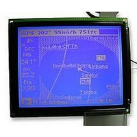
Description
LCD MODULE, 240X320, BLUE
Manufacturer
DENSITRON
Datasheet
1.LMR4769EW-WCB.pdf
(108 pages)
Specifications of LMR4769EW-WCB
Lcd Display Type
STN
Pixel Size (h X W)
0.34mm X 0.34mm
Display Mode
Transflective
Interface Type
Serial
Viewing Area (h X W)
92.14mm X 120.14mm
Supply Voltage
32V
External Depth
15.6mm
External
RoHS Compliant
Svhc
No SVHC (15-Dec-2010)
Rohs Compliant
Yes
Backlighting Colour
Blue
Pixel Pitch (h X W)
0.36mm X 0.36mm


S1D13700 Technical Manual
WR# (R/W#)
RD# (E)
CMF4
CS#
*A15–A0 are used as register addresses.
Input: CNF4 = 0 selects direct access; CNF4 = 1 selects indirect access.
<Direct access for the 68-series interface>
<Indirect access for the 68-series interface>
• When the 80-series MPU is connected
• When the 68-series MPU is connected
• When the MC68K-series MPU is connected
• When the 80-series MPU is connected
• When the 68-series MPU is connected
• When the MC68K-series MPU is connected
Input, active low
This chip select signal is used by the MPU to activate the S1D13700 before accessing it, and is normally
derived by decoding the address bus signal.
Input, active low
This is the strobe signal used by the MPU as it reads data or status flags from the S1D13700. The data bus
of the S1D13700 is in output mode while this signal remains low.
Input, active high
This is an enable clock input pin of the 68-series MPU.
Input, active low
Normally, this is an LDS# input pin of the MC68K-series MPU.
Input, active low
This is the strobe signal used by the 80-series MPU as it writes data or parameters to the S1D13700. The
S1D13700 latches the data bus signal at the rising edge of WR#.
Input
This is a R/W# control signal input pin of the 68-series MPU.
R/W# = HIGH : READ
R/W# = LOW : WRITE
Input
This is a R/W# control signal input pin of the MC68K-series MPU.
R/W# = HIGH : READ
R/W# = LOW : WRITE
CNF4
CNF4
0
0
1
1
1
1
AB15
AB15
– AB1
– AB1
0or1
0or1
–
–
–
–
AB0
0or1
0or1
AB0
0
1
0
1
(R/W#)
(R/W#)
WR#
WR#
1
0
1
1
0
0
EPSON
RD#
RD#
(E)
(E)
1
1
1
1
1
1
Read from command/parameter
registers
Write to command/parameter registers
Data (display data and cursor address)
read
Data (display data and parameter)
write
Command write (code only)
Function
Function
–
2: PINS
11
Related parts for LMR4769EW-WCB
Image
Part Number
Description
Manufacturer
Datasheet
Request
R

Part Number:
Description:
LCD MODULE, 128X240, YELLOW/GREEN
Manufacturer:
DENSITRON
Datasheet:

Part Number:
Description:
LCD MODULE, 128X240, BLUE
Manufacturer:
DENSITRON
Datasheet:

Part Number:
Description:
PMOLED, 128*128, COLOUR
Manufacturer:
DENSITRON
Datasheet:

Part Number:
Description:
DISPLAY, OLED, 128X32, BLUE
Manufacturer:
DENSITRON
Datasheet:
Part Number:
Description:
DISPLAY, OLED, 128X32, YLW
Manufacturer:
DENSITRON
Datasheet:
Part Number:
Description:
PMOLED, 128*64, WHITE
Manufacturer:
DENSITRON
Datasheet:
Part Number:
Description:
DISPLAY, OLED, 128X64, YELLOW
Manufacturer:
DENSITRON
Datasheet:

Part Number:
Description:
DISPLAY, OLED, 128X64, YELLOW
Manufacturer:
DENSITRON
Datasheet:
Part Number:
Description:
DISPLAY, OLED, 128X64, YELLOW
Manufacturer:
DENSITRON
Datasheet:
Part Number:
Description:
128 x 240 PIXEL INDUSTRIAL TOUCH MONITOR
Manufacturer:
Densitron Corporation
Part Number:
Description:
64 x 240 PIXEL INDUSTRIAL TOUCH MONITOR
Manufacturer:
Densitron Corporation
Part Number:
Description:
320 x 240 PIXEL INDUSTRIAL TOUCH MONITOR
Manufacturer:
Densitron Corporation
Part Number:
Description:
320 x 240 PIXEL INDUSTRIAL TOUCH MONITOR
Manufacturer:
Densitron Corporation
Part Number:
Description:
132 Seg / 65 Com Driver & Controller For Stn Lcd
Manufacturer:
Densitron Corporation
Datasheet: