LMR4769EW-WCB DENSITRON, LMR4769EW-WCB Datasheet - Page 4
LMR4769EW-WCB
Manufacturer Part Number
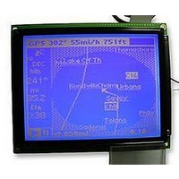
LMR4769EW-WCB
Description
LCD MODULE, 240X320, BLUE
Manufacturer
DENSITRON
Datasheet
1.LMR4769EW-WCB.pdf
(108 pages)
Specifications of LMR4769EW-WCB
Lcd Display Type
STN
Pixel Size (h X W)
0.34mm X 0.34mm
Display Mode
Transflective
Interface Type
Serial
Viewing Area (h X W)
92.14mm X 120.14mm
Supply Voltage
32V
External Depth
15.6mm
External
RoHS Compliant
Svhc
No SVHC (15-Dec-2010)
Rohs Compliant
Yes
Backlighting Colour
Blue
Pixel Pitch (h X W)
0.36mm X 0.36mm


1
2
3
4
5
6
S1D13700 Technical Manual
Overview ............................................................................................................................... 1
1.1
1.2
1.3
Pins ....................................................................................................................................... 5
2.1
2.2
Commands and Command Registers .............................................................................. 14
3.1
3.2
3.3
Function Description ......................................................................................................... 45
4.1
4.2
4.3
4.4
Specifications..................................................................................................................... 83
5.1
5.2
5.3
5.4
MPU Interface ..................................................................................................................... 95
6.1
6.2
Features ....................................................................................................................................... 1
System Overview ......................................................................................................................... 2
List of Abbreviations..................................................................................................................... 4
Pin Connection............................................................................................................................. 5
2.1.1
2.1.2
2.1.3
Pin Functions ............................................................................................................................... 9
2.2.1
2.2.2
2.2.3
2.2.4
2.2.5
Types of Commands (when Indirectly Interfaced) ...................................................................... 14
Command Register Map (when Directly Interfaced) .................................................................. 15
Command Description ............................................................................................................... 17
3.3.1
3.3.2
3.3.3
3.3.4
Display Functions....................................................................................................................... 45
4.1.1
4.1.2
4.1.3
4.1.4
4.1.5
4.1.6
4.1.7
4.1.8
Oscillator Circuit......................................................................................................................... 70
Example of Initial Settings.......................................................................................................... 71
Character Codes and Character Fonts ...................................................................................... 81
4.4.1
4.4.2
Absolute Maximum Ratings ....................................................................................................... 83
Recommended Operating Conditions........................................................................................ 83
Electrical Characteristics ........................................................................................................... 84
Timing Characteristics ............................................................................................................... 86
5.4.1
5.4.2
5.4.3
5.4.4
Connection to the System Bus................................................................................................... 95
6.1.1
6.1.2
Interfaces with the MPU (Reference) ......................................................................................... 96
Pin Assignments............................................................................................................. 5
Pin Description ............................................................................................................... 6
Package Dimensions...................................................................................................... 8
Power Supply Pins ......................................................................................................... 9
Oscillator and Clock Input Pins ...................................................................................... 9
System Bus Connecting Pins ....................................................................................... 10
LCD Driver Control Pins ............................................................................................... 13
TEST Control Pins........................................................................................................ 13
Operation Control Commands...................................................................................... 17
Display Control Commands.......................................................................................... 25
Drawing Control Commands ........................................................................................ 43
Memory Control Commands ........................................................................................ 44
Screen Management .................................................................................................... 45
Character Generator (CG)............................................................................................ 47
Screen Configuration.................................................................................................... 50
Cursor........................................................................................................................... 61
Relationship between Display Memory and Screens ................................................... 62
Determining Various Parameters.................................................................................. 64
Scrolling........................................................................................................................ 65
Attribute Display using the Layered Function ............................................................... 68
Character Fonts (Internal CG)...................................................................................... 81
Character Codes .......................................................................................................... 82
System Bus (Generic Bus/80-series MPU) .................................................................. 86
System Bus Read/write characteristics II (MC68K-series MPU).................................. 89
External Clock Input Characteristics ............................................................................ 92
LCD Control Signal Timing Characteristics .................................................................. 93
80-series MPU.............................................................................................................. 95
68-series MPU.............................................................................................................. 95
Table of Contents
EPSON
CONTENTS
i
Related parts for LMR4769EW-WCB
Image
Part Number
Description
Manufacturer
Datasheet
Request
R

Part Number:
Description:
LCD MODULE, 128X240, YELLOW/GREEN
Manufacturer:
DENSITRON
Datasheet:

Part Number:
Description:
LCD MODULE, 128X240, BLUE
Manufacturer:
DENSITRON
Datasheet:

Part Number:
Description:
PMOLED, 128*128, COLOUR
Manufacturer:
DENSITRON
Datasheet:

Part Number:
Description:
DISPLAY, OLED, 128X32, BLUE
Manufacturer:
DENSITRON
Datasheet:
Part Number:
Description:
DISPLAY, OLED, 128X32, YLW
Manufacturer:
DENSITRON
Datasheet:
Part Number:
Description:
PMOLED, 128*64, WHITE
Manufacturer:
DENSITRON
Datasheet:
Part Number:
Description:
DISPLAY, OLED, 128X64, YELLOW
Manufacturer:
DENSITRON
Datasheet:

Part Number:
Description:
DISPLAY, OLED, 128X64, YELLOW
Manufacturer:
DENSITRON
Datasheet:
Part Number:
Description:
DISPLAY, OLED, 128X64, YELLOW
Manufacturer:
DENSITRON
Datasheet:
Part Number:
Description:
128 x 240 PIXEL INDUSTRIAL TOUCH MONITOR
Manufacturer:
Densitron Corporation
Part Number:
Description:
64 x 240 PIXEL INDUSTRIAL TOUCH MONITOR
Manufacturer:
Densitron Corporation
Part Number:
Description:
320 x 240 PIXEL INDUSTRIAL TOUCH MONITOR
Manufacturer:
Densitron Corporation
Part Number:
Description:
320 x 240 PIXEL INDUSTRIAL TOUCH MONITOR
Manufacturer:
Densitron Corporation
Part Number:
Description:
132 Seg / 65 Com Driver & Controller For Stn Lcd
Manufacturer:
Densitron Corporation
Datasheet: