LMR4769EW-WCB DENSITRON, LMR4769EW-WCB Datasheet - Page 22
LMR4769EW-WCB
Manufacturer Part Number
LMR4769EW-WCB
Description
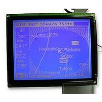
LCD MODULE, 240X320, BLUE
Manufacturer
DENSITRON
Datasheet
1.LMR4769EW-WCB.pdf
(108 pages)
Specifications of LMR4769EW-WCB
Lcd Display Type
STN
Pixel Size (h X W)
0.34mm X 0.34mm
Display Mode
Transflective
Interface Type
Serial
Viewing Area (h X W)
92.14mm X 120.14mm
Supply Voltage
32V
External Depth
15.6mm
External
RoHS Compliant
Svhc
No SVHC (15-Dec-2010)
Rohs Compliant
Yes
Backlighting Colour
Blue
Pixel Pitch (h X W)
0.36mm X 0.36mm


3.3
3.3.1
S1D13700 Technical Manual
Command Description
This command and the parameters that follow specify initial reset of the device, set the window size, and the
method of connecting with the LCD unit. This command determines the fundamental operation of the
S1D13700. Therefore, if this command is incorrectly set, the functions of other commands may not work
normally.
SYSTEM SET
<Indirect mode>
P1
P2
P3
P4
P5
P6
P7
P8
C
Operation Control Commands
C
MSB
WF
D7
0
0
0
The command alone has the following initial reset functions:
To deactivate sleep mode, make sure the command and one parameter (P1) are input.
In direct interface mode, clearing the SleepIn bit has the same effect.
• Resets the internal timing circuit.
• Turns display off.
• Deactivates sleep mode (internal operation stopped state) (thus starting the oscillator).
D6
0
1
0
0
D5
IV
0
0
0
D4
1
0
0
0
TC/R
C/R
L/F
APL
APH
W /S
D3
0
0
M2
D2
0
EPSON
FY
FX
M1
D1
0
M0
D0
0
3: COMMANDS AND COMMAND REGISTERS
LSB
<Direct mode>
0x8000
0x8001
0x8002
0x8003
0x8004
0x8005
0x8006
0x8007
Address
–
r_P1_SystemSet
r_P2_SystemSet
r_P3_SystemSet
r_P4_SystemSet
r_P5_SystemSet
r_P6_SystemSet
r_P7_SystemSet
r_P8_SystemSet
Register name
bit5 : IV
bit3 : WS
bit2 : M2
bit1 : M1
bit0 : M0
bit7 : WF
bit2-0 : FX
bit3-0 : FX
bit7-0 : CR
bit7-0 : TCR
bit7-0 : LF
bit7-0 : APL
bit7-0 : APH
–
17
Related parts for LMR4769EW-WCB
Image
Part Number
Description
Manufacturer
Datasheet
Request
R

Part Number:
Description:
LCD MODULE, 128X240, YELLOW/GREEN
Manufacturer:
DENSITRON
Datasheet:

Part Number:
Description:
LCD MODULE, 128X240, BLUE
Manufacturer:
DENSITRON
Datasheet:

Part Number:
Description:
PMOLED, 128*128, COLOUR
Manufacturer:
DENSITRON
Datasheet:

Part Number:
Description:
DISPLAY, OLED, 128X32, BLUE
Manufacturer:
DENSITRON
Datasheet:
Part Number:
Description:
DISPLAY, OLED, 128X32, YLW
Manufacturer:
DENSITRON
Datasheet:
Part Number:
Description:
PMOLED, 128*64, WHITE
Manufacturer:
DENSITRON
Datasheet:
Part Number:
Description:
DISPLAY, OLED, 128X64, YELLOW
Manufacturer:
DENSITRON
Datasheet:

Part Number:
Description:
DISPLAY, OLED, 128X64, YELLOW
Manufacturer:
DENSITRON
Datasheet:
Part Number:
Description:
DISPLAY, OLED, 128X64, YELLOW
Manufacturer:
DENSITRON
Datasheet:
Part Number:
Description:
128 x 240 PIXEL INDUSTRIAL TOUCH MONITOR
Manufacturer:
Densitron Corporation
Part Number:
Description:
64 x 240 PIXEL INDUSTRIAL TOUCH MONITOR
Manufacturer:
Densitron Corporation
Part Number:
Description:
320 x 240 PIXEL INDUSTRIAL TOUCH MONITOR
Manufacturer:
Densitron Corporation
Part Number:
Description:
320 x 240 PIXEL INDUSTRIAL TOUCH MONITOR
Manufacturer:
Densitron Corporation
Part Number:
Description:
132 Seg / 65 Com Driver & Controller For Stn Lcd
Manufacturer:
Densitron Corporation
Datasheet: