LMR4769EW-WCB DENSITRON, LMR4769EW-WCB Datasheet - Page 45
LMR4769EW-WCB
Manufacturer Part Number
LMR4769EW-WCB
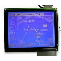
Description
LCD MODULE, 240X320, BLUE
Manufacturer
DENSITRON
Datasheet
1.LMR4769EW-WCB.pdf
(108 pages)
Specifications of LMR4769EW-WCB
Lcd Display Type
STN
Pixel Size (h X W)
0.34mm X 0.34mm
Display Mode
Transflective
Interface Type
Serial
Viewing Area (h X W)
92.14mm X 120.14mm
Supply Voltage
32V
External Depth
15.6mm
External
RoHS Compliant
Svhc
No SVHC (15-Dec-2010)
Rohs Compliant
Yes
Backlighting Colour
Blue
Pixel Pitch (h X W)
0.36mm X 0.36mm


3: COMMANDS AND COMMAND REGISTERS
40
P1
P2
C
<Indirect mode>
CGRAM ADR
DM1
DM2
OV
C
MSB
D7
A7
0
Specifies the display mode of the first screen block.
Specifies the display mode of the third screen block.
DM1 (block1)
DM2 (block3)
Note: The second and fourth screen blocks are limited to graphics mode.
Specifies a two-layer or three-layer composition in graphics mode.
OV
Note: Set OV = 0 for mixed text and graphics mode. When three-layer composition is
Defines the offset address of CG RAM in the display memory space.
A14
Note: For details on how to define CG RAM, see Section 4.1.2 “Character Generator
D6
A6
1
specified, both the first and third screen blocks should be set to the graphics
mode. (OV, DM2, DM1) = (1, 1, 1)
(CG)” on page 47.
A13
0: Tow-layer composition
1: Three-layer composition
D5
A5
0
A12
D4
A4
1
0: Text mode
1: Graphic mode
0: Text mode
1: Graphic mode
A11
D3
A3
1
A10
D2
A2
1
EPSON
D1
A1
A9
0
(SAGH)
(SAGL)
D0
A0
A8
0
LSB
<Direct mode>
0x8019
0x801A
Address
–
S1D13700 Technical Manual
r_P1_CGRAMAdr
r_P2_CGRAMAdr
Register name
bit7-0 : A7-A0
bit7-0 : A15-A8
–
Related parts for LMR4769EW-WCB
Image
Part Number
Description
Manufacturer
Datasheet
Request
R

Part Number:
Description:
LCD MODULE, 128X240, YELLOW/GREEN
Manufacturer:
DENSITRON
Datasheet:

Part Number:
Description:
LCD MODULE, 128X240, BLUE
Manufacturer:
DENSITRON
Datasheet:

Part Number:
Description:
PMOLED, 128*128, COLOUR
Manufacturer:
DENSITRON
Datasheet:

Part Number:
Description:
DISPLAY, OLED, 128X32, BLUE
Manufacturer:
DENSITRON
Datasheet:
Part Number:
Description:
DISPLAY, OLED, 128X32, YLW
Manufacturer:
DENSITRON
Datasheet:
Part Number:
Description:
PMOLED, 128*64, WHITE
Manufacturer:
DENSITRON
Datasheet:
Part Number:
Description:
DISPLAY, OLED, 128X64, YELLOW
Manufacturer:
DENSITRON
Datasheet:

Part Number:
Description:
DISPLAY, OLED, 128X64, YELLOW
Manufacturer:
DENSITRON
Datasheet:
Part Number:
Description:
DISPLAY, OLED, 128X64, YELLOW
Manufacturer:
DENSITRON
Datasheet:
Part Number:
Description:
128 x 240 PIXEL INDUSTRIAL TOUCH MONITOR
Manufacturer:
Densitron Corporation
Part Number:
Description:
64 x 240 PIXEL INDUSTRIAL TOUCH MONITOR
Manufacturer:
Densitron Corporation
Part Number:
Description:
320 x 240 PIXEL INDUSTRIAL TOUCH MONITOR
Manufacturer:
Densitron Corporation
Part Number:
Description:
320 x 240 PIXEL INDUSTRIAL TOUCH MONITOR
Manufacturer:
Densitron Corporation
Part Number:
Description:
132 Seg / 65 Com Driver & Controller For Stn Lcd
Manufacturer:
Densitron Corporation
Datasheet: