LMR4769EW-WCB DENSITRON, LMR4769EW-WCB Datasheet - Page 23
LMR4769EW-WCB
Manufacturer Part Number
LMR4769EW-WCB
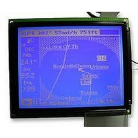
Description
LCD MODULE, 240X320, BLUE
Manufacturer
DENSITRON
Datasheet
1.LMR4769EW-WCB.pdf
(108 pages)
Specifications of LMR4769EW-WCB
Lcd Display Type
STN
Pixel Size (h X W)
0.34mm X 0.34mm
Display Mode
Transflective
Interface Type
Serial
Viewing Area (h X W)
92.14mm X 120.14mm
Supply Voltage
32V
External Depth
15.6mm
External
RoHS Compliant
Svhc
No SVHC (15-Dec-2010)
Rohs Compliant
Yes
Backlighting Colour
Blue
Pixel Pitch (h X W)
0.36mm X 0.36mm


3: COMMANDS AND COMMAND REGISTERS
Bank configurations
18
M2 M1 M0
0
0
0
1
[Parameter P1]
The table below summarizes bank configurations by M1, M2, and M3.
0
0
M0
M1
M2
External
External
Internal
Internal
ROM
RAM
ROM
RAM
Specify the CG ROM to be used for display. Although internal CG ROM can generate 160
discrete character fonts (each consisting of 5 x 7 dots as shown in Section 4.4.1 “Character
Fonts (Internal CG)” on page 81), internal CG RAM may be used when different character
fonts or more characters (up to 256) are needed.
M0
Note: When the CG area is mapped in the display memory space, the memory area
Selects the CG RAM definition area where the user can define any desired character pattern.
The CG RAM code may be selected from the 64 discrete codes assigned in Section 4.4.2
“Character Codes” on page 82.
M1
Select the CG size in the Y direction for more economical use of internal CG RAM. CGs whose
sizes in the Y direction are 17 dots or more cannot be handled with the character codes of the
S1D13700. In such case, characters may be decomposed into bit images and displayed in
graphic display mode of the S1D13700.
M2
160 characters (5 x 7 x 160)
64 characters (8 x 6 x 64)
160 characters (5 x 7 x 160)
64 characters (6 x 8 x 64)
available to store display data is reduced by the amount of CG area mapped.
0: Internal CG ROM (160 characters) + internal CG RAM (64 characters)
1: Internal CG RAM (256 characters)
0: Without bit D6 correction The CG RAM1 and CG RAM2 areas are noncontiguous.
1: With bit D6 correction
0: 8 dots
1: 16 dots
EPSON
10 – 1F
20 – 2F
30 – 3F
40 – 4F
50 – 5F
60 – 6F
70 – 7F
A0 – AF
B0 – BF
C0 – CF
D0 – DF
SAG+ { [80 – 8F], Row [2 : 0]}
Same as shown above.
SAG+ { [A0 – AF], Row [2 : 0]}
Only CG RAM1 is handled as CG RAM, with CG RAM2
handled as CG ROM.
The CG RAM1 and CG RAM2 areas are contiguous.
Both CG RAM1 and RAM2 are handled as CG RAM.
[90 – 9F]
[E0 – EF]
[F0 – FF]
[B0 – BF]
[C0 – CF]
[D0 – DF]
S1D13700 Technical Manual
Internal ROM used
Without correction
Y size = 8
Internal ROM used
With correction
Y size = 8
Related parts for LMR4769EW-WCB
Image
Part Number
Description
Manufacturer
Datasheet
Request
R

Part Number:
Description:
LCD MODULE, 128X240, YELLOW/GREEN
Manufacturer:
DENSITRON
Datasheet:

Part Number:
Description:
LCD MODULE, 128X240, BLUE
Manufacturer:
DENSITRON
Datasheet:

Part Number:
Description:
PMOLED, 128*128, COLOUR
Manufacturer:
DENSITRON
Datasheet:

Part Number:
Description:
DISPLAY, OLED, 128X32, BLUE
Manufacturer:
DENSITRON
Datasheet:
Part Number:
Description:
DISPLAY, OLED, 128X32, YLW
Manufacturer:
DENSITRON
Datasheet:
Part Number:
Description:
PMOLED, 128*64, WHITE
Manufacturer:
DENSITRON
Datasheet:
Part Number:
Description:
DISPLAY, OLED, 128X64, YELLOW
Manufacturer:
DENSITRON
Datasheet:

Part Number:
Description:
DISPLAY, OLED, 128X64, YELLOW
Manufacturer:
DENSITRON
Datasheet:
Part Number:
Description:
DISPLAY, OLED, 128X64, YELLOW
Manufacturer:
DENSITRON
Datasheet:
Part Number:
Description:
128 x 240 PIXEL INDUSTRIAL TOUCH MONITOR
Manufacturer:
Densitron Corporation
Part Number:
Description:
64 x 240 PIXEL INDUSTRIAL TOUCH MONITOR
Manufacturer:
Densitron Corporation
Part Number:
Description:
320 x 240 PIXEL INDUSTRIAL TOUCH MONITOR
Manufacturer:
Densitron Corporation
Part Number:
Description:
320 x 240 PIXEL INDUSTRIAL TOUCH MONITOR
Manufacturer:
Densitron Corporation
Part Number:
Description:
132 Seg / 65 Com Driver & Controller For Stn Lcd
Manufacturer:
Densitron Corporation
Datasheet: