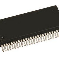
MM908E625ACDWB Freescale Semiconductor, MM908E625ACDWB Datasheet - Page 28

MM908E625ACDWB
Manufacturer Part Number
MM908E625ACDWB
Description
IC QUAD HALF BRDG MCU/LIN 54SOIC
Manufacturer
Freescale Semiconductor
Datasheets
1.MM908E625.pdf
(48 pages)
2.MM908E625ACDWB.pdf
(48 pages)
3.MM908E625ACDWB.pdf
(48 pages)
4.MM908E625ACDWB.pdf
(48 pages)
5.MM908E625ACDWB.pdf
(40 pages)
Specifications of MM908E625ACDWB
Applications
Automotive Mirror Control
Core Processor
HC08
Program Memory Type
FLASH (16 kB)
Controller Series
908E
Ram Size
512 x 8
Interface
SCI, SPI
Number Of I /o
13
Voltage - Supply
8 V ~ 18 V
Operating Temperature
-40°C ~ 85°C
Mounting Type
Surface Mount
Package / Case
54-SOIC (0.300", 7.50mm Width) Exposed Pad
Program Memory Size
16 KB
Number Of Programmable I/os
54
Number Of Timers
16
Operating Supply Voltage
- 18 V to + 28 V
Maximum Operating Temperature
+ 85 C
Mounting Style
SMD/SMT
Minimum Operating Temperature
- 40 C
Lead Free Status / RoHS Status
Contains lead / RoHS non-compliant
Available stocks
Company
Part Number
Manufacturer
Quantity
Price
Company:
Part Number:
MM908E625ACDWB
Manufacturer:
FREESCALE Semiconductor
Quantity:
26
POWER OUTPUT REGISTER (POUT)
Current Source Select Bits (CSSEL0:CSSEL1)
Reset clears the CSSEL0:CSSEL1 bits.
Reset clears the CSEN bit
Table 9. PA1 Current Source Enable Bit
HVDDON bit.
28
Notes
Current Source Enable Bit (CSEN)
HVDD On Bit (HVDDON)
908E625
FUNCTIONAL DEVICE OPERATION
LOGIC COMMANDS AND REGISTERS
Reset
Write
Read
Bits
15.
CSEN
These read/write bits select the current source values.
This read/write bit enables the current source for PA1.
This read/write bit enables HVDD output. Reset clears the
• 1 = HVDD enabled
• 0 = HVDD disabled
0
1
This bit must always be set to 0.
7
0
0
Register Name and Address: POUT - $0b
6
0
0
CSSEL1 CSSEL0 CSEN
5
0
Current Source Enable
4
0
(Table
Current Source Off
Current Source On
3
0
9).
0
(15)
2
0
HVDDON HS_ON
1
0
0
0
the HS_ON bit.
Hall-Effect Sensor Input Terminals (H1:H3)
Function
for two-terminal Hall-effect sensors for detecting stall and
position or reading Hall-effect sensor contact switches. The
Hall-effect sensor input terminals are not influenced by the
PSON bit in the System Control Register.
setting the HxEN bit in the Hall-Effect Sensor Input Terminal
Control Register (HACTL). If the terminals are enabled, the
Hall-effect sensors are supplied with V
sense circuitry is working. An internal clamp circuity limits the
supply voltage to the sensor to 15 V. This sense circuitry
monitors the current to VSS. The result of this sense
operation is given by the HxF flags in the Hall-Effect Sensor
Input Terminal Status Register (HASTAT).
To prevent noise on this flag, a hysteresis is implemented on
these terminals.
(HxEN = 1), the Hall-effect sensors need some time to
stabilize the output. In RUN mode the software must wait at
least 40 µs between enabling the Hall-effect sensor and
reading the hall flag.
output voltage range from V
the hallflags are not functional anymore. If the output voltage
is below a certain threshold, the Hall-Effect Sensor Input
Terminal Overcurrent Flag (HP_OCF) in the System Status
Register is set.
Hall-effect input sensors.
Lamp Driver On Bit (HS_ON)
This read/write bit enables the Lamp driver. Reset clears
• 1 = Lamp driver enabled
• 0 = Lamp driver disabled
The Hall-effect sensor input terminals provide three inputs
Each terminal of the Hall-effect sensor can be enabled by
The flag is set if the sensed current is higher than I
After switching on the Hall-effect sensor input terminals
The Hall-effect sensor input terminal works in an dynamic
Figures 13
through
15
Analog Integrated Circuit Device Data
illustrate the connections to the
SUP
down to 2.0 V. Below 2.0 V
Freescale Semiconductor
SUP
voltage and the
HSCT
.


