ISL12023IVZ Intersil, ISL12023IVZ Datasheet - Page 10
ISL12023IVZ
Manufacturer Part Number
ISL12023IVZ
Description
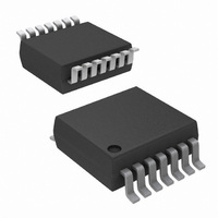
IC RTC/CLDR TEMP SNSR 14-TSSOP
Manufacturer
Intersil
Type
Clock/Calendarr
Datasheet
1.ISL12023IVZ.pdf
(28 pages)
Specifications of ISL12023IVZ
Memory Size
1K (128 x 8)
Time Format
HH:MM:SS (12/24 hr)
Date Format
YY-MM-DD-dd
Interface
I²C, 2-Wire Serial
Voltage - Supply
2.7 V ~ 5.5 V
Operating Temperature
-40°C ~ 85°C
Mounting Type
Surface Mount
Package / Case
14-TSSOP
Lead Free Status / RoHS Status
Lead free / RoHS Compliant
Available stocks
Company
Part Number
Manufacturer
Quantity
Price
Company:

Part Number:
ISL12023IVZ
Manufacturer:
Intersil
Quantity:
341


The device Time Stamps the switchover from V
and V
registers respectively. If multiple V
sequences occur before status is read, the earliest V
V
to V
Temperature conversion and compensation can be enabled
in battery-backup mode. Bit BTSE in the BETA register
controls this operation, as described in “BETA Register
(BETA)” on page 17.
Power Failure Detection
The ISL12023 provides a Real Time Clock Failure Bit
(RTCF) to detect total power failure. It allows users to
determine if the device has powered up after having lost all
power to the device (both V
Brownout Detection
The ISL12023 monitors the V
provides warning if the V
levels. There are six (6) levels that can be selected for the
trip level. These values are 85% below popular V
The LVDD bit in the Status Register will be set to “1” when
brownout is detected. Note that the I
active unless the Battery V
LVRST output becomes active (LOW) when the Power
Brownout Bit (LVDD) is set.
When the V
V
LVDD bit is reset once it is read by the Micro. Note that the
I
are reached.
Battery Level Monitor
The ISL12023 has a built in warning feature once the backup
battery level drops first to 85% and then to 75% of the
battery’s nominal VBAT level. When the battery voltage
drops to between 85% and 75%, the LBAT85 bit is set in the
status register. When the level drops below 75%, both
LBAT85 and LBAT75 bits are set in the status register.
The battery level monitor is not functional in battery backup
mode. In order to read the monitor bits after powering up
V
TSE bit to "1" (BETA register), and then read the bits.
There is a Battery Time Stamp Function available. Once the
V
RTC time/date are written into the TSV2B register. This
information can be read from the TSV2B registers to
discover the point in time of the V
are multiple power-down cycles before reading these
registers, the first values stored in these registers will be
retained. These registers will hold the original power-down
value until they are cleared by setting CLRTS = 1 to clear the
registers.
2
BAT
DD
DD
DD
C serial bus remains active unless the Battery V
DD
, instigate a battery level measurement by setting the
+ 50mV trip point, the LVRST output is set HIGH. The
is low enough to enable switchover to the battery, the
BAT
power-down time is stored and the most recent V
time is stored.
to V
DD
DD
power is re-established and is above the 85%
, and the time is stored in t
DD
TRIP
DD
level drops below prescribed
10
DD
and V
levels are reached. The
level continuously and
DD
DD
2
BAT
power-down. If there
C serial bus remains
power-down
).
SV2B
DD
DD
TRIP
and t
to V
DD
levels.
levels
BAT
SB2V
BAT
to
ISL12023
The normal power switching of the ISL12023 is designed to
switch into battery-backup mode only if the V
lost. This will ensure that the device can accept a wide range
of backup voltages from many types of sources while reliably
switching into backup mode.
Note that the ISL12023 is not guaranteed to operate with
V
than this minimum, correct operation of the device,
especially after a V
The minimum V
that, the SRAM may be corrupted when V
Real Time Clock Operation
The Real Time Clock (RTC) uses an external 32.768kHz
quartz crystal to maintain an accurate internal representation
of second, minute, hour, day of week, date, month, and year.
The RTC also has leap-year correction. The clock also
corrects for months having fewer than 31 days and has a bit
that controls 24-hour or AM/PM format. When the ISL12023
powers up after the loss of both V
not begin incrementing until at least one byte is written to the
clock register.
Single Event and Interrupt
The alarm mode is enabled via the MSB bit. Choosing single
event or interrupt alarm mode is selected via the IM bit. Note
that when the frequency output function is enabled, the
alarm function is disabled.
The standard alarm allows for alarms of time, date, day of
the week, month, and year. When a time alarm occurs in
single event mode, an IRQ pin will be pulled low and the
alarm status bit (ALM) will be set to “1”.
The pulsed interrupt mode allows for repetitive or recurring
alarm functionality. Hence, once the alarm is set, the device
will continue to alarm for each occurring match of the alarm
and present time. Thus, it will alarm as often as every minute
(if only the nth second is set) or as infrequently as once a
year (if at least the nth month is set). During pulsed interrupt
mode, the IRQ pin will be pulled low for 250ms and the alarm
status bit (ALM) will be set to “1”.
The ALM bit can be reset by the user or cleared
automatically using the auto reset mode (see ARST bit). The
alarm function can be enabled/disabled during
battery-backup mode using the FOBATB bit. For more
information on the alarm, please see “ALARM Registers
(10h to 15h)” on page 19.
Frequency Output Mode
The ISL12023 has the option to provide a clock output signal
using the F
mode is set by using the FO bits to select one of 15 possible
output frequency values from 1/32Hz to 32kHz. The
frequency output can be enabled/disabled during
battery-backup mode using the FOBATB bit.
BAT
< 1.8V. If the battery voltage is expected to drop lower
OUT
BAT
open drain output pin. The frequency output
DD
to insure SRAM is stable is 1.0V. Below
power down cycle, is not guaranteed.
DD
and V
DD
BAT
power resumes.
DD
, the clock will
power is
June 24, 2009
FN6682.2
Related parts for ISL12023IVZ
Image
Part Number
Description
Manufacturer
Datasheet
Request
R

Part Number:
Description:
Intersil Corporation [CMOS Serial Controller Interface]
Manufacturer:
Intersil Corporation
Datasheet:
Part Number:
Description:
Manufacturer:
Intersil Corporation
Datasheet:
Part Number:
Description:
357-036-542-201 CARDEDGE 36POS DL .156 BLK LOPRO
Manufacturer:
Intersil Corporation
Datasheet:
Part Number:
Description:
1024-Word x 4-Bit LSI Static RAM
Manufacturer:
Intersil Corporation
Datasheet:
Part Number:
Description:
General Purpose NPN Transistor Arrays FN341.4
Manufacturer:
Intersil Corporation
Datasheet:
Part Number:
Description:
CMOS 16-Bit Microprocessor
Manufacturer:
Intersil Corporation
Datasheet:
Part Number:
Description:
Manufacturer:
Intersil Corporation
Datasheet:
Part Number:
Description:
Manufacturer:
Intersil Corporation
Datasheet:
Part Number:
Description:
Manufacturer:
Intersil Corporation
Datasheet:
Part Number:
Description:
Manufacturer:
Intersil Corporation
Datasheet:
Part Number:
Description:
CMOS 6-Bit Latch and Decoder Memory Interfaces
Manufacturer:
Intersil Corporation
Datasheet:
Part Number:
Description:
CA3046General Purpose NPN Transistor Arrays
Manufacturer:
Intersil Corporation
Datasheet:
Part Number:
Description:
Manufacturer:
Intersil Corporation
Datasheet:
Part Number:
Description:
TR909 DLC/FLC SLIC with Low Power Standby
Manufacturer:
Intersil Corporation
Datasheet:
Part Number:
Description:
Manufacturer:
Intersil Corporation
Datasheet: