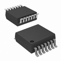
ISL12023IVZ Intersil, ISL12023IVZ Datasheet - Page 18

ISL12023IVZ
Manufacturer Part Number
ISL12023IVZ
Description
IC RTC/CLDR TEMP SNSR 14-TSSOP
Manufacturer
Intersil
Type
Clock/Calendarr
Datasheet
1.ISL12023IVZ.pdf
(28 pages)
Specifications of ISL12023IVZ
Memory Size
1K (128 x 8)
Time Format
HH:MM:SS (12/24 hr)
Date Format
YY-MM-DD-dd
Interface
I²C, 2-Wire Serial
Voltage - Supply
2.7 V ~ 5.5 V
Operating Temperature
-40°C ~ 85°C
Mounting Type
Surface Mount
Package / Case
14-TSSOP
Lead Free Status / RoHS Status
Lead free / RoHS Compliant
Available stocks
Company
Part Number
Manufacturer
Quantity
Price
Company:
Part Number:
ISL12023IVZ
Manufacturer:
Intersil
Quantity:
341
BETA values are limited in the range from 01000 to 11111 as
shown in Table 16
two AT settings as follows:
BETA VALUES = (AT(max) - AT(min))/63, where:
AT(max) = F
AT(min) = F
The BETA VALUES result is indexed in the right hand
column and the resulting Beta factor (for the register) is in
the same row in the left column.
The value for BETA should only be changed while the TSE
(Temp Sense Enable) bit is “0”. The procedure for writing the
BETA register involves two steps. First, write the new value
of BETA with TSE = 0. Then write the same value of BETA
with TSE = 1. This will insure the next temp sense cycle will
use the new BETA value
BETA<4:0>
OUT
OUT
01000
00110
00101
00100
00011
00010
00001
00000
10000
10001
10010
10011
10100
10101
10110
11000
11001
11010
00111
10111
11011
11100
11101
11110
11111
in ppm (at AT = 3FH).
in ppm (at AT = 00H) and
TABLE 16. BETA VALUES
.
To use Table 16, the device is tested at
.
18
AT STEP ADJUSTMENT
0.5000
0.5625
0.6250
0.6875
0.7500
0.8125
0.8750
0.9375
1.0000
1.0625
1.1250
1.1875
1.2500
1.3125
1.3750
1.4375
1.5000
1.5625
1.6250
1.6875
1.7500
1.8125
1.8750
1.9375
2.0000
ISL12023
Final Analog Trimming Register (FATR)
This register shows the final setting of AT after temperature
correction. It is read-only, the user cannot overwrite a value to
this register. This value is accessible as a means of monitoring
the temperature compensation function. See Table 17.
Final Digital Trimming Register (FDTR)
This register shows the final setting of DT after temperature
correction. It is read-only; the user cannot overwrite a value to
this register. The value is accessible as a means of monitoring
the temperature compensation function. The corresponding
clock adjustment values are shown in Table 19. The DT
setting has both positive and negative settings to adjust for
any offset in the crystal.
.
ADDR
ADDR
TABLE 19. CLOCK ADJUSTMENT VALUES FOR FINAL
0Eh
0Fh
FDTR<2:0>
TABLE 17. FINAL ANALOG TRIMMING REGISTER
TABLE 18. FINAL DIGITAL TRIMMING REGISTER
00000
00001
00010
00011
00100
00101
00110
01000
01001
01010
10000
10001
10010
10011
10100
10101
10110
11000
11001
11010
00111
10111
7
0
7
0
DIGITAL TRIMMING REGISTER
6
0
6
0
FATR5 FATR4 FATR3 FATR2 FATR1 FATR0
5
5
0
FDTR4 FDTR3 FDTR2 FDTR1 FDTR0
4
DECIMAL
4
-10
10
-1
-2
-3
-4
-5
-6
-7
-8
-9
0
1
2
3
4
5
6
7
8
9
0
3
3
2
2
ADJUSTMENT
-152.5
-213.5
-274.5
(ppm)
152.5
213.5
274.5
-30.5
-91.5
-122
-183
-244
-305
30.5
91.5
1
122
183
244
305
-61
61
1
0
0
June 24, 2009
FN6682.2
0
0


