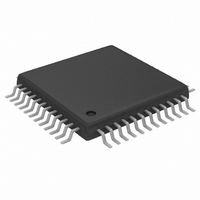
MAX5858AECM+TD Maxim Integrated Products, MAX5858AECM+TD Datasheet - Page 14

MAX5858AECM+TD
Manufacturer Part Number
MAX5858AECM+TD
Description
IC DAC 10BIT DUAL 300MSPS 48TQFP
Manufacturer
Maxim Integrated Products
Datasheet
1.MAX5858AECMD.pdf
(25 pages)
Specifications of MAX5858AECM+TD
Settling Time
11ns
Number Of Bits
10
Data Interface
Parallel
Number Of Converters
2
Voltage Supply Source
Single Supply
Power Dissipation (max)
816mW
Operating Temperature
-40°C ~ 85°C
Mounting Type
Surface Mount
Package / Case
48-TQFP Exposed Pad, 48-eTQFP, 48-HTQFP, 48-VQFP
Lead Free Status / RoHS Status
Lead free / RoHS Compliant
The MAX5858A dual, high-speed, 10-bit, current-output
DAC provides superior performance in communication
systems requiring low-distortion analog-signal recon-
struction. The MAX5858A combines two DAC cores with
2x/4x programmable digital interpolation filters, a PLL
clock multiplier, divide-by-N clock output, and an on-
chip 1.24V reference. The current outputs of the DACs
can be configured for differential or single-ended opera-
tion. The full-scale output current range is adjustable
from 2mA to 20mA to optimize power dissipation and
gain control.
The MAX5858A accepts an input data rate of up to
165MHz or a DAC conversion rate of up to 300MHz. The
inputs are latched on the rising edge of the clock where-
as the output latches on the following rising edge.
The two-stage digital interpolation filters are program-
mable to 4x, 2x, or no interpolation. When operating in
4x interpolation mode, the interpolator increases the
DAC conversion rate by a factor of four, providing a
four-fold increase in separation between the recon-
structed waveform spectrum and its first image.
The on-chip PLL clock multiplier generates and distrib-
utes all internal, synchronized high-speed clock signals
required by the input data latches, interpolation filters,
Dual, 10-Bit, 300Msps, DAC with 4x/2x/1x
Interpolation Filters and PLL
14
______________________________________________________________________________________
DA9–DA0
DB9–DB0
CW
IDE
Detailed Description
DV
MAX5858A
DD
10
10
CONTROL REGISTER
DGND
PV
DD
REGISTER
REGISTER
INPUT
INPUT
AV
DD
10
10
F1EN
PGND
INTERPOLATION
INTERPOLATION
2x DIGITAL
2x DIGITAL
FILTER
FILTER
1.2V REFERENCE AND CONTROL AMPLIFIER
10
10
and DAC cores. The on-chip PLL includes phase-detec-
tor, VCO, prescalar, and charge-pump circuits. The PLL
can be enabled or disabled through PLLEN.
The analog and digital sections of the MAX5858A have
separate power-supply inputs (AV
a separate supply input is provided for the PLL clock
multiplier (PV
a 2.7V to 3.3V single supply.
The MAX5858A features three modes of operation: nor-
mal, standby, and power-down. These modes allow effi-
cient power management. In power-down, the MAX5858A
consumes only 1µA of supply current. Wake-up time from
standby mode to normal DAC operation is 0.7µs.
An 8-bit control word routed through channel A’s data
port programs the gain matching, interpolator configura-
tion, and operational mode of the MAX5858A. The con-
trol word is latched on the falling edge of CW. Table 1
describes the control word format and function.
The gain on channel A can be adjusted to achieve gain
matching between two channels in a user’s system.
The gain on channel A can be adjusted from +0.4dB to
-0.35dB in steps of 0.05dB by using bits G3 to G0 (see
Table 3).
F2EN
REFO
INTERPOLATION
INTERPOLATION
2x DIGITAL
2x DIGITAL
FILTER
FILTER
CLKXP
PLL CLOCK MULTIPLIER
REN
CLKXN
10
10
DD
). AV
REFR
CLK
300MHz
300MHz
10-BIT
10-BIT
DAC
DAC
DD
, DV
R
SET
Programming the DAC
DD
, and PV
AGND
Block Diagram
DD
LOCK
PLLEN
PLLF
OUTPA
OUTNA
OUTPB
OUTNB
and DV
DD
operate from
DD
). Also,


