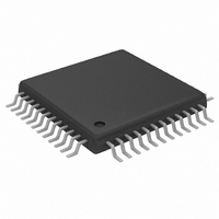
MAX5858AECM+TD Maxim Integrated Products, MAX5858AECM+TD Datasheet - Page 23

MAX5858AECM+TD
Manufacturer Part Number
MAX5858AECM+TD
Description
IC DAC 10BIT DUAL 300MSPS 48TQFP
Manufacturer
Maxim Integrated Products
Datasheet
1.MAX5858AECMD.pdf
(25 pages)
Specifications of MAX5858AECM+TD
Settling Time
11ns
Number Of Bits
10
Data Interface
Parallel
Number Of Converters
2
Voltage Supply Source
Single Supply
Power Dissipation (max)
816mW
Operating Temperature
-40°C ~ 85°C
Mounting Type
Surface Mount
Package / Case
48-TQFP Exposed Pad, 48-eTQFP, 48-HTQFP, 48-VQFP
Lead Free Status / RoHS Status
Lead free / RoHS Compliant
The MAX5858A is packaged in a 48-pin TQFP-EP pack-
age, providing design flexibility, increased thermal effi-
ciency, and optimized AC performance of the DAC. The
EP enables the implementation of grounding techniques,
which are necessary to ensure highest performance
operation.
In this package, the data converter die is attached to
an EP leadframe with the back of the frame exposed at
the package bottom surface, facing the PC board side
of the package. This allows a solid attachment of the
package to the PC board with standard infrared (IR)-
flow soldering techniques. A specially created land pat-
tern on the PC board, matching the size of the EP,
ensures the proper attachment and grounding of the
DAC. Designing vias* into the land area and imple-
menting large ground planes in the PC board design
achieve optimal DAC performance. Use an array of 3
3 (or greater) vias (0.3mm diameter per via hole and
1.2mm pitch between via holes) for this 48-pin TQFP-
EP package.
Commonly used in combination with wideband code-
division multiple-access (WCDMA), ACLR reflects the
leakage power ratio in dB between the measured
power within a channel relative to its adjacent channel.
ACLR provides a quantifiable method of determining
out-of-band spectral energy and its influence on an
adjacent channel when a bandwidth-limited RF signal
passes through a nonlinear device.
THD is the ratio of the RMS sum of all essential harmon-
ics (within a Nyquist window) of the input signal to the
fundamental itself. This can be expressed as:
where V
V
harmonics.
*Vias connect the land pattern to internal or external copper planes.
N
THD
are the amplitudes of the 2nd through Nth-order
=
1
is the fundamental amplitude, and V
20
Adjacent Channel Leakage Ratio (ACLR)
Dynamic Performance Parameter
×
Dual, 10-Bit, 300Msps, DAC with 4x/2x/1x
log
______________________________________________________________________________________
Total Harmonic Distortion (THD)
V
2
2
+
V
3
2
+
V
4
2
... ...
+
Definitions
V
N
2
2
Interpolation Filters and PLL
through
/
V
1
✕
SFDR is the ratio of RMS amplitude of the carrier fre-
quency (maximum signal component) to the RMS value
of the next-largest spectral component. SFDR is usually
measured in dBc with respect to the carrier frequency
amplitude or in dB FS with respect to the DAC’s full-
scale range. Depending on its test condition, SFDR is
observed within a predefined window or to Nyquist.
A series of equally spaced tones are applied to the DAC
with one tone removed from the center of the range.
MTPR is defined as the worst-case distortion (usually a
3rd-order harmonic product of the fundamental frequen-
cies), which appears as the largest spur at the frequency
of the missing tone in the sequence. This test can be per-
formed with any number of input tones; however, four and
eight tones are among the most common test conditions
for CDMA- and GSM/EDGE-type applications.
The two-tone IMD is the ratio expressed in dBc of either out-
put tone to the worst 3rd-order (or higher) IMD products.
Integral nonlinearity (INL) is the deviation of the values
on an actual transfer function from a line drawn
between the end points of the transfer function, once
offset and gain errors have been nullified. For a DAC,
the deviations are measured at every individual step.
Differential nonlinearity (DNL) is the difference between
an actual step height and the ideal value of 1 LSB. A
DNL error specification no more negative than -1 LSB
guarantees monotonic transfer function.
Offset error is the current flowing from positive DAC
output when the digital input code is set to zero. Offset
error is expressed in LSBs.
Static Performance Parameter Definitions
Intermodulation Distortion (IMD)
Spurious-Free Dynamic Range (SFDR)
Multitone Power Ratio (MTPR)
Differential Nonlinearity (DNL)
Integral Nonlinearity (INL)
Offset Error
23


