DP83849CVS/NOPB National Semiconductor, DP83849CVS/NOPB Datasheet - Page 9
DP83849CVS/NOPB
Manufacturer Part Number
DP83849CVS/NOPB
Description
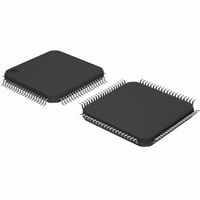
IC TXRX ETHERNET PHY DUAL 80TQFP
Manufacturer
National Semiconductor
Type
Transceiverr
Specifications of DP83849CVS/NOPB
Number Of Drivers/receivers
2/2
Protocol
Ethernet
Voltage - Supply
3 V ~ 3.6 V
Mounting Type
Surface Mount
Package / Case
80-TQFP, 80-VQFP
Data Rate
100Mbps
Supply Voltage Range
3V To 3.6V
Logic Case Style
TQFP
No. Of Pins
80
Operating Temperature Range
0°C To +70°C
Msl
MSL 3 - 168 Hours
Filter Terminals
SMD
Rohs Compliant
Yes
Data Rate Max
10Mbps
For Use With
DP83849CVS-EVK - BOARD EVALUATION DP83849CVS
Lead Free Status / RoHS Status
Lead free / RoHS Compliant
Other names
*DP83849CVS
*DP83849CVS/NOPB
DP83849CVS
*DP83849CVS/NOPB
DP83849CVS
Available stocks
Company
Part Number
Manufacturer
Quantity
Price
Company:

Part Number:
DP83849CVS/NOPB
Manufacturer:
NS
Quantity:
618
Company:
Part Number:
DP83849CVS/NOPB
Manufacturer:
Texas Instruments
Quantity:
10 000


1.0 Pin Descriptions
The DP83849C pins are classified into the following inter-
face categories (each interface is described in the sections
that follow):
— Serial Management Interface
— MAC Data Interface
— Clock Interface
— LED Interface
— Reset and Power Down
— Strap Options
— 10/100 Mb/s PMD Interface
— Special Connect Pins
— Power and Ground pins
Note: Strapping pin option. Please see Section 1.6 for strap
definitions.
1.1 Serial Management Interface
1.2 MAC Data Interface
MDC
MDIO
TX_CLK_A
TX_CLK_B
TX_EN_A
TX_EN_B
TXD[3:0]_A
TXD[3:0]_B
Signal Name
Signal Name
Type
Type
I/O
O
I
I
I
17,16,15,14
45,46,47,48
Pin #
Pin #
67
66
12
50
13
49
MANAGEMENT DATA CLOCK: Synchronous clock to the MDIO
management data input/output serial interface which may be asyn-
chronous to transmit and receive clocks. The maximum clock rate is
25 MHz with no minimum clock rate.
MANAGEMENT DATA I/O: Bi-directional management instruc-
tion/data signal that may be sourced by the station management entity
or the PHY. This pin requires a 1.5 k pullup resistor.
MII TRANSMIT CLOCK: 25 MHz Transmit clock output in 100 Mb/s
mode or 2.5 MHz in 10 Mb/s mode derived from the 25 MHz reference
clock.
Unused in RMII mode. The device uses the X1 reference clock input
as the 50 MHz reference for both transmit and receive.
SNI TRANSMIT CLOCK: 10 MHz Transmit clock output in 10 Mb SNI
mode. The MAC should source TX_EN and TXD_0 using this clock.
MII TRANSMIT ENABLE: Active high input indicates the presence of
valid data inputs on TXD[3:0].
RMII TRANSMIT ENABLE: Active high input indicates the presence
of valid data on TXD[1:0].
SNI TRANSMIT ENABLE: Active high input indicates the presence of
valid data on TXD_0.
MII TRANSMIT DATA: Transmit data MII input pins, TXD[3:0], that
accept data synchronous to the TX_CLK (2.5 MHz in 10 Mb/s mode
or 25 MHz in 100 Mb/s mode).
RMII TRANSMIT DATA: Transmit data RMII input pins, TXD[1:0],
that accept data synchronous to the 50 MHz reference clock.
SNI TRANSMIT DATA: Transmit data SNI input pin, TXD_0, that ac-
cept data synchronous to the TX_CLK (10 MHz in 10 Mb/s SNI mode).
9
All DP83849C signal pins are I/O cells regardless of the
particular use. The definitions below define the functionality
of the I/O cells for each pin.
Type: I
Type: O
Type: I/O
Type OD
Type: PD,PU Internal Pulldown/Pullup
Type: S
Input
Output
Input/Output
Open Drain
Strapping Pin (All strap pins have weak in-
ternal pull-ups or pull-downs. If the default
strap value is to be changed then an exter-
nal 2.2 k
see Section 1.6 for details.)
Description
Description
resistor should be used. Please
www.national.com
Related parts for DP83849CVS/NOPB
Image
Part Number
Description
Manufacturer
Datasheet
Request
R

Part Number:
Description:
National Semiconductor [8-Bit D/A Converter]
Manufacturer:
National Semiconductor
Datasheet:
Part Number:
Description:
National Semiconductor [Media Coprocessor]
Manufacturer:
National Semiconductor
Datasheet:
Part Number:
Description:
Digitally Controlled Tone and Volume Circuit with Stereo Audio Power Amplifier, Microphone Preamp Stage and National 3D Sound
Manufacturer:
National Semiconductor
Datasheet:
Part Number:
Description:
Digitally Controlled Tone and Volume Circuit with Stereo Audio Power Amplifier, Microphone Preamp Stage and National 3D Sound
Manufacturer:
National Semiconductor
Datasheet:
Part Number:
Description:
AC97 Rev 2 Codec with Sample Rate Conversion and National 3D Sound
Manufacturer:
National Semiconductor
Part Number:
Description:
Manufacturer:
National Semiconductor
Datasheet:
Part Number:
Description:
Manufacturer:
National Semiconductor
Datasheet:
Part Number:
Description:
General Purpose, Low Voltage, Low Power, Rail-to-Rail Output Operational Amplifiers
Manufacturer:
National Semiconductor
Datasheet:
Part Number:
Description:
8-bit 20 MSPS flash A/D converter.
Manufacturer:
National Semiconductor
Datasheet:
Part Number:
Description:
Low Noise Quad Operational Amplifier
Manufacturer:
National Semiconductor
Datasheet:
Part Number:
Description:
Quad Differential Line Receivers
Manufacturer:
National Semiconductor
Datasheet:
Part Number:
Description:
Quad High Speed Trapezoidal? Bus Transceiver
Manufacturer:
National Semiconductor
Datasheet:
Part Number:
Description:
Dual Line Receiver
Manufacturer:
National Semiconductor
Datasheet:
Part Number:
Description:
TTL to 10k ECL Level Translator with Latch
Manufacturer:
National Semiconductor
Datasheet: