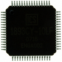
ICS1893CY-10LF IDT, Integrated Device Technology Inc, ICS1893CY-10LF Datasheet - Page 110

ICS1893CY-10LF
Manufacturer Part Number
ICS1893CY-10LF
Description
PHYCEIVER LOW PWR 3.3V 64-TQFP
Manufacturer
IDT, Integrated Device Technology Inc
Series
PHYceiver™r
Type
PHY Transceiverr
Datasheet
1.ICS1893CY-10LFT.pdf
(143 pages)
Specifications of ICS1893CY-10LF
Protocol
MII
Voltage - Supply
3.14 V ~ 3.47 V
Mounting Type
Surface Mount
Package / Case
64-TQFP, 64-VQFP
Lead Free Status / RoHS Status
Lead free / RoHS Compliant
Number Of Drivers/receivers
-
Lead Free Status / RoHS Status
Compliant, Lead free / RoHS Compliant
Other names
1893CY-10LF
800-1025
800-1025
Available stocks
Company
Part Number
Manufacturer
Quantity
Price
Company:
Part Number:
ICS1893CY-10LF
Manufacturer:
IDT
Quantity:
469
Company:
Part Number:
ICS1893CY-10LF
Manufacturer:
IDT, Integrated Device Technology Inc
Quantity:
10 000
Company:
Part Number:
ICS1893CY-10LFT
Manufacturer:
IDT, Integrated Device Technology Inc
Quantity:
10 000
8.3.4.2 MAC/Repeater Interface Pins for 100M Symbol Interface
ICS1893CY-10 Rev 1/07
Table 8-5. MAC/Repeater Interface Pins: Media Independent Interface (MII) (Continued)
Table 8-6
Table 8-6. MAC/Repeater Interface Pins: 100M Symbol Interface
TXEN
TXER
COL
CRS
MDC
MDIO
RXCLK
MII Pin
Name
Name
Pin
ICS1893CY-10 Data Sheet - Release
lists the MAC/Repeater Interface pin descriptions for the 100M Symbol Interface.
Number
–
SCRS
MDC
MDIO
SRCLK
Symbol
Pin
Name
100M
44
42
Pin
Type
Input
Input
Pin
No.
Pin
49
50
31
30
38
Copyright © 2007, Integrated Device Technology, Inc.
Connect
Transmit Enable.
In MII mode:
Transmit Error.
When the MAC/Repeater Interface is in:
Output
Output
Output
Input/
Type
Input
•
•
•
•
Note: The Invalid Symbol used for this function is the HALT symbol,
Pin
No
The ICS1893CY-10 samples its TXEN signal to determine when data
is available for transmission. When TXEN is asserted, the
ICS1893CY-10 begins sampling the data nibbles on the transmit data
lines TXD[3:0] synchronously with TXCLK. The ICS1893CY-10 then
transmits this data over the media.
Following the de-assertion of TXEN, the ICS1893CY-10 terminates
transmission of nibbles over the media.
10M MII mode, TXER is not used.
100M MII mode:
– The ICS1893CY-10 synchronously samples its TXER signal on the
– The assertion of TXER by the MAC/repeater causes the
– the Invalid Error Code Test bit (bit 16.2) is set to logic one, the 5-bit
rising edges of its TXCLK signal.
ICS1893CY-10 to transmit an Invalid Symbol.
symbol shown in the Invalid Error Code Translation Table
7-17) is used instead of the normal 4B/5B encoding described in the
ISO/IEC specification.
which is substituted for the transmit nibble received from the
MAC/repeater whenever the TXER is asserted.
Collision (Detect).
For the 100M Symbol Interface, this pin is a no connect. For
more information, see
Symbol Carrier Sense.
This pin’s description is the same as that given in
Management Data Clock.
This pin’s description is the same as that given in
Management Data Input/Output.
This pin’s description is the same as that given in
(Symbol) Receive Clock.
In Symbol Mode, the ICS1893CY-10 sources an SRCLK to a
MAC/repeater. The SRCLK synchronizes the signals on the
SRD[4:0] pins between the ICS1893CY-10 and the
MAC/repeater. The SRCLK frequency is 25MHz.
All rights reserved.
110
Chapter 8 Pin Diagram, Listings, and Descriptions
Pin Description
Table
Pin Description
5-1.
Table
Table
Table
(Table
8-5.
8-5.
8-5.


