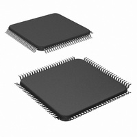
DS90C387RVJDX/NOPB National Semiconductor, DS90C387RVJDX/NOPB Datasheet - Page 24

DS90C387RVJDX/NOPB
Manufacturer Part Number
DS90C387RVJDX/NOPB
Description
IC LDI DUAL PIXAL 3.3V 100-TQFP
Manufacturer
National Semiconductor
Datasheet
1.DS90C387RVJDXNOPB.pdf
(28 pages)
Specifications of DS90C387RVJDX/NOPB
Applications
Displays
Interface
2-Wire Serial
Voltage - Supply
3 V ~ 3.6 V
Package / Case
100-TQFP, 100-VQFP
Mounting Type
Surface Mount
Lead Free Status / RoHS Status
Lead free / RoHS Compliant
Other names
DS90C387RVJDX
Available stocks
Company
Part Number
Manufacturer
Quantity
Price
Company:
Part Number:
DS90C387RVJDX/NOPB
Manufacturer:
Texas Instruments
Quantity:
10 000
www.national.com
Applications Information
How to configure the DS90C387R to work with
DS90CF384/DS90CF384A/DS90CF386 or DS90CF388 for
most common application:
1. To configure for single pixel application using the
DS90C387R to interface with GMCH host, please see table
below for reference pin connection and configuration. Due to
the implementation differences among various GMCH ven-
dors, the table is using the GMCH vendor located in Santa
Clara, California, USA as an example. A two-wire serial
communication interface based EEPROM containing EDID
128 bytes LCD timing information may be required depend-
ing on device driver implementation.
From DS90C387R
DDRENI2Cclk
RESERVED1
RESERVED2
RESERVED3
RESERVED4
RESERVED5
RESERVED6
RESERVED7
RESERVED8
RESERVED9
DSELI2Cdat
D12 to D23
CLKINM
CLKINP
PLLSEL
HSYNC
VSYNC
DUAL
TST1
TST2
BAL
D10
D11
DE
D0
D1
D2
D3
D4
D5
D6
D7
D8
D9
A0
A1
A2
configuration for other pins
data signal connection
No connect
No connect
No connect
To GMCH
I2CDATA
HSYNC
VSYHC
I2CCLK
BLANK
CLK1
CLK0
GND
GND
GND
GND
GND
GND
GND
GND
GND
GND
GND
GND
GND
D10
D11
Vcc
Vcc
D0
D1
D2
D3
D4
D5
D6
D7
D8
D9
24
2. To configure for single pixel application using the
DS90C387R with single DS90CF384 or DS90CF384A or
DS90CF386 LVDS based LCD panel or monitor, the “DUAL”
pin must be set to Gnd (single RGB), and “BAL” pin must be
set to Gnd to disable the feature for DS90CF384/
DS90CF386 doesn’t support DC balance function. For cable
length more than two meters, pre-emphasis feature is rec-
ommended. Please see table below for reference pin con-
nection.
3. To configure for single pixel or dual pixel application using
the DS90C387R with DS90CF388, the “DUAL” pin must be
set to Vcc (dual RGB) or Gnd (single RGB). Also, “BAL” pins
on both devices have to in the same logic state. For cable
length more than two meters, pre-emphasis feature is rec-
ommended.
4. In dual mode, DS90C387R has two LVDS clock outputs
enabling an interface to two FPD-Link ’notebook’ receivers
(DS90CF384/DS90CF386). “BAL” pin must be set to Gnd to
disable DC balance function for DS90CF384/DS90CF386
doesn’t support DC balance function. In single mode, out-
puts A4-to-A7 and CLK2 are disabled which reduces power
dissipation. For cable length more than two meters, pre-
emphasis feature is recommended.
The DS90CF388 is able to support single or dual pixel
interface up to 112MHz operating frequency. This receiver
may also be used to interface to a VGA controller with an
From DS90C387R Output
only; no connect for 6-bit
only; no connect for 6-bit
A3M(valid for 8-bit LCD
A3P(valid for 8-bit LCD
CLK1M
CLK2M
CLK1P
CLK2P
MSEN
VREF
LCD)
LCD)
A0M
A1M
A2M
A4M
A5M
A6M
A7M
Pins
A0P
A1P
A2P
A4P
A5P
A6P
A7P
data signal connection
RxIN3−(valid for 8-bit LCD
RxIN3+(valid for 8-bit LCD
only; no connect for 6-bit
only; no connect for 6-bit
To LVDS based LCD
RxCLKIN0−
RxCLKIN0+
No connect
No connect
No connect
No connect
No connect
No connect
No connect
No connect
No connect
No connect
monitor
RxIN0−
RxIN0+
RxIN1−
RxIN1+
RxIN2−
RxIN2+
VREF
LCD)
LCD)
INT#


