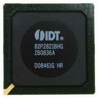
IDT82P2821BHG IDT, Integrated Device Technology Inc, IDT82P2821BHG Datasheet - Page 32

IDT82P2821BHG
Manufacturer Part Number
IDT82P2821BHG
Description
IC LINE INTERFACE UNIT 640-PBGA
Manufacturer
IDT, Integrated Device Technology Inc
Datasheet
1.IDT82P2821BHG.pdf
(151 pages)
Specifications of IDT82P2821BHG
Function
Line Interface Unit (LIU)
Interface
E1, J1, T1
Number Of Circuits
1
Voltage - Supply
1.8V, 3.3V
Operating Temperature
-40°C ~ 85°C
Mounting Type
Surface Mount
Package / Case
*
Includes
Defect and Alarm Detection, Driver Over-Current Detection and Protection, LLOS Detection, PRBSARB / IB Detection and Generation
Number Of Transceivers
1
Screening Level
Industrial
Mounting
Surface Mount
Operating Temperature (min)
-40C
Operating Temperature (max)
85C
Lead Free Status / RoHS Status
Lead free / RoHS Compliant
Current - Supply
-
Power (watts)
-
Lead Free Status / RoHS Status
Compliant, Lead free / RoHS Compliant
Other names
800-1703
82P2821BHG
82P2821BHG
Available stocks
Company
Part Number
Manufacturer
Quantity
Price
Company:
Part Number:
IDT82P2821BHG
Manufacturer:
IDT
Quantity:
170
Company:
Part Number:
IDT82P2821BHG
Manufacturer:
IDT, Integrated Device Technology Inc
Quantity:
10 000
3.2.2
receive sensitivity.
3.2.2.1 Line Monitor
Intrusive Monitoring per T1.102 can be performed between two devices.
The monitored channel of one device is in normal operation, and the
monitoring channel of the other device taps the monitored one through a
high impedance bridging circuit (refer to Figure-13 and Figure-14).
RRINGn of the monitoring channel is dramatically attenuated. To
compensate this bridge resistive attenuation, Monitor Gain can be used
to boost the signal by 20 dB, 26 dB or 32 dB, as selected by the MG[1:0]
bits (b1~0, RCF2,...). For normal operation, the Monitor Gain should be
set to 0 dB, i.e., the Monitor Gain of the monitored channel should be 0
dB.
Partially Internal or Fully Internal Impedance Matching mode. Here the
external r or internal IM is used for voltage division, not for impedance
matching. That is, the r (IM) and the two R make up of a resistance
bridge. The resistive attenuation of this bridge is 20lg(r/(2R+r)) dB.
Channel 0 Monitoring). If multiple High-Density LIUs are used in an
application, The G.772 function of channel 0 can be used to route the
signals of channel 1~21 Receive and Transmit to channel 0 of the same
device. This channel 0 Transmit TTIP and TTRING could then be moni-
tored by another device through the Line Monitor function.
3.2.2.2 Receive Sensitivity
for which the receiver recovers data error-free with -18 dB interference
signal added.
dB.
dB.
Functional Description
IDT82P2821
The equalizer compensates high frequency attenuation to enhance
In both T1/J1 and E1 short haul applications, the Protected Non-
After the high resistance bridging circuit, the signal arriving at RTIPn/
The monitoring channel can be configured to any of the External,
Note that line monitor is only available in differential line interface.
A channel 0 monitoring function is provided (refer to Section 3.5.9
The receive sensitivity is the minimum range of receive signal level
For Receive Differential line interface, the receive sensitivity is -15
For Receive Single Ended line interface, the receive sensitivity is -12
EQUALIZER
21(+1) CHANNEL HIGH-DENSITY T1/E1/J1 LINE INTERFACE UNIT
32
connect point
connect point
R
DSX cross
DSX cross
Figure-14 Transmit Path Monitoring
Figure-13 Receive Path Monitoring
R
R
R
RRINGn
RRINGn
RRINGn
RTIPn
RTIPn
r
r
RTIPn
TTIPn
TRINGn
monitoring channel
= 20/26/32 dB
monitoring channel
= 20/26/32 dB
monitor gain
monitored channel
monitored channel
monitor gain
monitor gain
monitor gain
= 0 dB
February 6, 2009
= 0 dB


