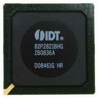
IDT82P2821BHG IDT, Integrated Device Technology Inc, IDT82P2821BHG Datasheet - Page 71

IDT82P2821BHG
Manufacturer Part Number
IDT82P2821BHG
Description
IC LINE INTERFACE UNIT 640-PBGA
Manufacturer
IDT, Integrated Device Technology Inc
Datasheet
1.IDT82P2821BHG.pdf
(151 pages)
Specifications of IDT82P2821BHG
Function
Line Interface Unit (LIU)
Interface
E1, J1, T1
Number Of Circuits
1
Voltage - Supply
1.8V, 3.3V
Operating Temperature
-40°C ~ 85°C
Mounting Type
Surface Mount
Package / Case
*
Includes
Defect and Alarm Detection, Driver Over-Current Detection and Protection, LLOS Detection, PRBSARB / IB Detection and Generation
Number Of Transceivers
1
Screening Level
Industrial
Mounting
Surface Mount
Operating Temperature (min)
-40C
Operating Temperature (max)
85C
Lead Free Status / RoHS Status
Lead free / RoHS Compliant
Current - Supply
-
Power (watts)
-
Lead Free Status / RoHS Status
Compliant, Lead free / RoHS Compliant
Other names
800-1703
82P2821BHG
82P2821BHG
Available stocks
Company
Part Number
Manufacturer
Quantity
Price
Company:
Part Number:
IDT82P2821BHG
Manufacturer:
IDT
Quantity:
170
Company:
Part Number:
IDT82P2821BHG
Manufacturer:
IDT, Integrated Device Technology Inc
Quantity:
10 000
4.3
be provided for the IDT82P2821. A Power-on reset will be initiated
during power up. Refer to Section 4.1 Reset.
4.4
MARY
becoming increasingly important. To combat these problems, redun-
dancy protection must be built into the systems carrying this traffic.
There are many types of redundancy protection schemes, including 1+1
and 1:1 hardware protection without the use of external relays. Refer to
Miscellaneous
IDT82P2821
No power up sequencing for the VDD inputs (1.8 V and 3.3 V) has to
In today’s telecommunication systems, ensuring no traffic loss is
Rx: Partially Internal Impedance Matching mode. A fixed external 120 Ω resistor is placed on the backplane and provides a common termination for
T1/J1/E1 applications. The R_TERM[2:0] bits (b2~0, RCF0,...) setting is as follows: ‘000’ for T1 100 Ω twisted pair cable, ‘001’ for J1 110 Ω twisted
pair cable, ‘010’ for E1 120 Ω twisted pair cable and ‘011’ for E1 75 Ω coaxial cable.
Tx: Internal Impedance Matching mode. The
for J1 110 Ω twisted pair cable, ‘010’ for E1 120 Ω twisted pair cable and ‘011’ for E1 75 Ω coaxial cable.
POWER UP
HITLESS PROTECTION SWITCHING (HPS) SUM-
Hot switch control
Figure-46 1+1 HPS Scheme, Differential Interface (Shared Common Transformer)
T_TERM[2:0] bits (b2~0, TCF0,...) setting is as follows:
RIM
OE
RIM
OE
LIU on backup line card
LIU on primary line card
21(+1) CHANNEL HIGH-DENSITY T1/E1/J1 LINE INTERFACE UNIT
Tx
Rx
Tx
Rx
71
Figure-46, Figure-47 and Figure-48 for different protection schemes.
The IDT82P2821 provides an enhanced architecture to support both
protection schemes.
IDT82P2821 highlights for HPS support:
• Independent programmable receive and transmit high impedance
• Fully integrated receive termination, required to support 1:1 redun-
• Enhanced internal architecture to guarantee High Impedance for
• Asynchronous hardware control (OE, RIM) for fast global high
for Tip and Ring inputs and outputs to support 1+1 and 1:1 redun-
dancy
dancy
Tip and Ring Inputs and Outputs during Power Off or Power Fail-
ure
impedance of receiver and transmitter (hot switching between
working and backup board)
VDDRn
VDDRn
VDDTn
•
•
•
•
VDDTn
VDDRn
VDDRn
VDDTn
VDDTn
•
•
•
•
‘000’ for T1 100 Ω twisted pair cable, ‘001’
backplane
120 Ω
interface card
February 6, 2009
1:2
1:1


