FPS100024 TDK Corporation, FPS100024 Datasheet - Page 10
FPS100024
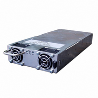
Manufacturer Part Number
FPS100024
Description
PWR SUP FNT END 24V 960W 40A
Manufacturer
TDK Corporation
Series
FPSr
Type
Commercialr
Datasheets
1.FPS100024.pdf
(57 pages)
2.FPS100024.pdf
(2 pages)
3.FPS100024.pdf
(1 pages)
4.FPS100048.pdf
(3 pages)
Specifications of FPS100024
Power Supply Type
Switching (Closed Frame)
Voltage - Output
24V
Number Of Outputs
1
Power (watts)
1000W
Applications
Commercial
Voltage - Input
85 ~ 265VAC
Mounting Type
Chassis Mount
1st Output
24 VDC @ 40A
Size / Dimension
1.61" L x 5" W x 11.4" H (40.9mm x 127mm x 289.6mm)
Power (watts) - Rated
960W
Operating Temperature
0°C ~ 70°C
Efficiency
86%
Approvals
CE, EN, UL
Line Regulation
0.4%
Load Regulation
0.8%
Power Supply Output Type
Fixed
No. Of Outputs
1
Output Voltage
24V
Output Current
40A
Power Rating
960W
Input Voltage
85V AC - 265V AC / 120V DC To 360V DC.
Brand/series
FPS1000 Series
Configuration
Enclosed
Operation
Linear
Output
24 VDC @ 40 A
Power, Output
960 W
Primary Type
AC-DC
Special Features
High Efficiency, Hot Swappable, PFC, Remote On/Off, Remote Sense
Voltage, Input
85 to 265/120 to 360 VAC/VDC
Voltage, Output
24 VDC
Lead Free Status / RoHS Status
Lead free / RoHS Compliant
3rd Output
-
2nd Output
-
4th Output
-
Lead Free Status / Rohs Status
RoHS Compliant part
Other names
285-1237
Available stocks
Company
Part Number
Manufacturer
Quantity
Price
Company:

Part Number:
FPS100024
Manufacturer:
TDK-LAMBDA
Quantity:
232
Company:
Part Number:
FPS100024/P
Manufacturer:
TDK-LAMBDA
Quantity:
232
Company:
Part Number:
FPS100024/PS
Manufacturer:
TDK-LAMBDA
Quantity:
232
Company:
Part Number:
FPS100024/S
Manufacturer:
TDK-LAMBDA
Quantity:
232


CHAPTER 3
3.1 GENERAL
This chapter contains instructions for initial inspection, preparation for use and repackaging forshipment.
3.2 PREPARATION FOR USE
In order to be operational the power supply must be connected to an appropriate AC source.
The AC source voltage should be within the power supply specification. Do not apply power before reading
sections 3.6 and 3.7.
Table 3-1 below describes the basic setup procedure. Follow the instructions in Table 3-1 in the sequence
given to prepare the power supply for use.
3.3 INITIAL INSPECTION
Prior to shipment this power supply was inspected and found free of mechanical or electrical defects.
Upon unpacking of the power supply, inspect for any damage which may have occurred in transit.
The inspection should confirm that there is no exterior damage to the power supply.
Keep all packing material until the inspection has been completed. If damage is detected , file a claim with
carrier immediately and notify the Lambda sales or service facility nearest you.
3.4 FPS1000 MOUNTING
The FPS1000 power supplies series is designed to fit in the FPS-S1U and FPS-T1U, 19" rack, or in an
equivalent rack designed for the FPS1000 power supply.
The FPS1000 is secured to the rack using the spring lock device, located at the FPS1000 front panel.
Refer to the FPS1000 and the FPS-S1U and FPS-T1U outline drawings in Chapter 2, Chapter 11 and
Chapter 18.
When installation using mounting screws is required, the FPS1000 can be secured to the equipment using
the M3 mounting holes at its bottom surface. Refer to the FPS1000 outline drawings.
3.5 LOCATION MOUNTING AND COOLING
This power supply is fan cooled. The air intake is at the front panel and the exhaust is at the rear panel.
Upon installation allow cooling air to reach the front panel ventilation inlets and allow minimum 50mm of
unrestricted air space at the rear of the unit for the air exhaust.
3.6 AC SOURCE REQUIREMENTS
The FPS1000 series can be operated from a nominal 100V to 240V, single phase, 47~63Hz. Refer to the
specifications in chapter 1 for the input voltage range and the current required.
Ensure that under heavy load, the AC voltage supplied to the power supply does not fall below the "low
limit" specifications.
Connection of this power supply to an AC
power source should be made by an
electrician or other qualified personnel.
Table 3-1: Basic setup procedure
Step no
CAUTION
1
2
3
4
Item
Inspection
Installation
AC source
Load connection
FPS1000 POWER SUPPLY INSTALLATION
FPS1000 power supplies series generate magnetic field
which might affect the operation of other instruments.
If your equipment is susceptible to magnetic fields, do
not position it adjacent to the FPS1000 unit.
Description
Initial physical inspection of the power supply
Installing the power supply.
Ensuring adequate ventilation.
AC source requirements
Wire size selection. Local / Remote
sensing. Single or multiple loads.
There is a potential shock hazard if the power supply
chassis and cover are not connected to an electrical safety
ground via the safetyground in the AC input connector.
NOTE
WARNING
7
FPS1000 Instruction Manual
Reference
Section 3.3
Section 3.4
Section 3.7
Section 3.5
Section 3.6
Related parts for FPS100024
Image
Part Number
Description
Manufacturer
Datasheet
Request
R

Part Number:
Description:
TDK DC to DC Converters, DC to AC Inverters
Manufacturer:
TDK Corporation
Datasheet:
Part Number:
Description:
TDK DC to DC Converters, DC to AC Inverters
Manufacturer:
TDK Corporation
Datasheet: