FPS100024 TDK Corporation, FPS100024 Datasheet - Page 16
FPS100024
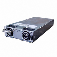
Manufacturer Part Number
FPS100024
Description
PWR SUP FNT END 24V 960W 40A
Manufacturer
TDK Corporation
Series
FPSr
Type
Commercialr
Datasheets
1.FPS100024.pdf
(57 pages)
2.FPS100024.pdf
(2 pages)
3.FPS100024.pdf
(1 pages)
4.FPS100048.pdf
(3 pages)
Specifications of FPS100024
Power Supply Type
Switching (Closed Frame)
Voltage - Output
24V
Number Of Outputs
1
Power (watts)
1000W
Applications
Commercial
Voltage - Input
85 ~ 265VAC
Mounting Type
Chassis Mount
1st Output
24 VDC @ 40A
Size / Dimension
1.61" L x 5" W x 11.4" H (40.9mm x 127mm x 289.6mm)
Power (watts) - Rated
960W
Operating Temperature
0°C ~ 70°C
Efficiency
86%
Approvals
CE, EN, UL
Line Regulation
0.4%
Load Regulation
0.8%
Power Supply Output Type
Fixed
No. Of Outputs
1
Output Voltage
24V
Output Current
40A
Power Rating
960W
Input Voltage
85V AC - 265V AC / 120V DC To 360V DC.
Brand/series
FPS1000 Series
Configuration
Enclosed
Operation
Linear
Output
24 VDC @ 40 A
Power, Output
960 W
Primary Type
AC-DC
Special Features
High Efficiency, Hot Swappable, PFC, Remote On/Off, Remote Sense
Voltage, Input
85 to 265/120 to 360 VAC/VDC
Voltage, Output
24 VDC
Lead Free Status / RoHS Status
Lead free / RoHS Compliant
3rd Output
-
2nd Output
-
4th Output
-
Lead Free Status / Rohs Status
RoHS Compliant part
Other names
285-1237
Available stocks
Company
Part Number
Manufacturer
Quantity
Price
Company:

Part Number:
FPS100024
Manufacturer:
TDK-LAMBDA
Quantity:
232
Company:
Part Number:
FPS100024/P
Manufacturer:
TDK-LAMBDA
Quantity:
232
Company:
Part Number:
FPS100024/PS
Manufacturer:
TDK-LAMBDA
Quantity:
232
Company:
Part Number:
FPS100024/S
Manufacturer:
TDK-LAMBDA
Quantity:
232


4.11 Remote Sensing
The Remote sensing compensates voltage drop on the load wiring. The maximum voltage drop on each wire is 1V,
however, it is recommended to minimize the voltage drop on the load wires to improve the response to load current
changes.
In case that the sensing wires are long, use separate twisted pair wires for the sensing and for the load wires to
minimize noise pick-up.
It is recommended to connect electrolytic capacitors in the following locations:
Refer to Fig 4-6 for typical connection of remote sensing.
Fig 4-6
FPS1000
1) Across the load terminals
2) Between the "+S" terminal and the "+V" terminal of the power supply.
3) Between the "-S" terminal and the "-V" terminal of the power supply.
+S
+V
-V
-S
1,2,4
3,5,6
13
8
+
+
13
FPS1000 Instruction Manual
+
-
LOAD
Related parts for FPS100024
Image
Part Number
Description
Manufacturer
Datasheet
Request
R

Part Number:
Description:
TDK DC to DC Converters, DC to AC Inverters
Manufacturer:
TDK Corporation
Datasheet:
Part Number:
Description:
TDK DC to DC Converters, DC to AC Inverters
Manufacturer:
TDK Corporation
Datasheet: