APMOTOR56F8000E Freescale Semiconductor, APMOTOR56F8000E Datasheet - Page 115
APMOTOR56F8000E
Manufacturer Part Number
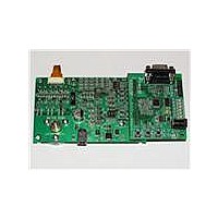
APMOTOR56F8000E
Description
KIT DEMO MOTOR CTRL SYSTEM
Manufacturer
Freescale Semiconductor
Type
Motor / Motion Controllers & Driversr
Datasheets
1.CWH-UTP-ONCE-HE.pdf
(2 pages)
2.APMOTOR56F8000E.pdf
(124 pages)
3.APMOTOR56F8000E.pdf
(2 pages)
Specifications of APMOTOR56F8000E
Accessory Type
Motor Controller
Input Voltage
9 V
Interface Type
RS-232
Product
Power Management Modules
For Use With/related Products
DEMO56F8013, DEMO56F8013-E
Lead Free Status / RoHS Status
Lead free / RoHS Compliant


A, the internal [static component], is comprised of the DC bias currents for the oscillator, leakage currents,
PLL, and voltage references. These sources operate independently of processor state or operating
frequency.
B, the internal [state-dependent component], reflects the supply current required by certain on-chip
resources only when those resources are in use. These include RAM, Flash memory and the ADCs.
C, the internal [dynamic component], is classic C*V
56800E core and standard cell logic.
D, the external [dynamic component], reflects power dissipated on-chip as a result of capacitive loading
on the external pins of the chip. This is also commonly described as C*V
of the I/O cell types used on the 56800E reveal that the power-versus-load curve does have a non-zero
Y-intercept.
Power due to capacitive loading on output pins is (first order) a function of the capacitive load and
frequency at which the outputs change.
in the I/O cells as a function of capacitive load. In these cases:
where:
Because of the low duty cycle on most device pins, power dissipation due to capacitive loads was found
to be fairly low when averaged over a period of time.
E, the external [static component], reflects the effects of placing resistive loads on the outputs of the
device. Sum the total of all V
for the purposes of these rough calculations. For instance, if there is a total of eight PWM outputs driving
10mA into LEDs, then P = 8*.5*.01 = 40mW.
Freescale Semiconductor
•
•
•
Summation is performed over all output pins with capacitive loads
TotalPower is expressed in mW
Cload is expressed in pF
+D: external [dynamic component]
+C: internal [dynamic component]
+E: external [static]
TotalPower = Σ((Intercept + Slope*Cload)*frequency/10MHz)
Table 10-20 I/O Loading Coefficients at 10MHz
8mA drive
4mA drive
2
/R or IV to arrive at the resistive load contribution to power. Assume V = 0.5
56F8014 Technical Data, Rev. 11
Table 10-20
provides coefficients for calculating power dissipated
2
Intercept
1.15mW
*F CMOS power dissipation corresponding to the
1.3
0.11mW / pF
0.11mW / pF
Slope
2
*F, although simulations on two
Power Consumption
115
Related parts for APMOTOR56F8000E
Image
Part Number
Description
Manufacturer
Datasheet
Request
R

Part Number:
Description:
Manufacturer:
Freescale Semiconductor, Inc
Datasheet:
Part Number:
Description:
Manufacturer:
Freescale Semiconductor, Inc
Datasheet:
Part Number:
Description:
Manufacturer:
Freescale Semiconductor, Inc
Datasheet:
Part Number:
Description:
Manufacturer:
Freescale Semiconductor, Inc
Datasheet:
Part Number:
Description:
Manufacturer:
Freescale Semiconductor, Inc
Datasheet:
Part Number:
Description:
Manufacturer:
Freescale Semiconductor, Inc
Datasheet:
Part Number:
Description:
Manufacturer:
Freescale Semiconductor, Inc
Datasheet:
Part Number:
Description:
Manufacturer:
Freescale Semiconductor, Inc
Datasheet:
Part Number:
Description:
Manufacturer:
Freescale Semiconductor, Inc
Datasheet:
Part Number:
Description:
Manufacturer:
Freescale Semiconductor, Inc
Datasheet:
Part Number:
Description:
Manufacturer:
Freescale Semiconductor, Inc
Datasheet:
Part Number:
Description:
Manufacturer:
Freescale Semiconductor, Inc
Datasheet:
Part Number:
Description:
Manufacturer:
Freescale Semiconductor, Inc
Datasheet:
Part Number:
Description:
Manufacturer:
Freescale Semiconductor, Inc
Datasheet:
Part Number:
Description:
Manufacturer:
Freescale Semiconductor, Inc
Datasheet: