APMOTOR56F8000E Freescale Semiconductor, APMOTOR56F8000E Datasheet - Page 74
APMOTOR56F8000E
Manufacturer Part Number
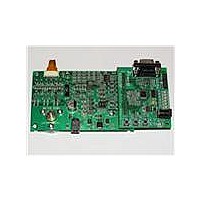
APMOTOR56F8000E
Description
KIT DEMO MOTOR CTRL SYSTEM
Manufacturer
Freescale Semiconductor
Type
Motor / Motion Controllers & Driversr
Datasheets
1.CWH-UTP-ONCE-HE.pdf
(2 pages)
2.APMOTOR56F8000E.pdf
(124 pages)
3.APMOTOR56F8000E.pdf
(2 pages)
Specifications of APMOTOR56F8000E
Accessory Type
Motor Controller
Input Voltage
9 V
Interface Type
RS-232
Product
Power Management Modules
For Use With/related Products
DEMO56F8013, DEMO56F8013-E
Lead Free Status / RoHS Status
Lead free / RoHS Compliant


6.3.8.13
These bits select the alternate function for GPIOA4.
Note:
6.3.9
The Peripheral Clock Enable register is used to enable or disable clocks to the peripherals as a power
savings feature. The clocks can be individually controlled for each peripheral on the chip. The
corresponding peripheral should itself be disabled while its clock is shut off.
6.3.9.1
6.3.9.2
This bit field is reserved or not implemented. It is read as 0 and cannot be modified by writing.
6.3.9.3
6.3.9.4
This bit field is reserved or not implemented. It is read as 0 and cannot be modified by writing.
6.3.9.5
74
•
•
•
•
•
•
•
•
•
•
Base + $C
RESET
Read
Write
11 = T3 — Timer Channel 3 input/output
00 = PWM4 — PWM4 output
01 = PWM4 — PWM4 output
10 = FAULT1 — PWM FAULT1 input
11 = T2 — Timer Channel 2 input/output
0 = The clock is not provided to the I
1 = Clocks to the I
0 = The clock is not provided to the ADC module (the ADC module is disabled)
1 = Clocks to the ADC module are enabled
0 = The clock is not provided to the Quad Timer module (the Quad Timer module is disabled)
When programming the CFG_* signals be careful so as not to connect two different I/O pins to the
same peripheral input. For example, do not set CFG_B7 to select SCL and also set CFG_B0 to select
SCL. If this occurs for an output signal, then the signal will be routed to two I/O pins. For input
signals, the values on the two I/O pins will be ORed together before reaching the peripheral.
Peripheral Clock Enable Register (SIM_PCE)
Configure GPIOA4[1:0] (CFG_A4)—Bits 1–0
I
Reserved—Bit 14
Analog-to-Digital Converter IPBus Clock Enable (ADC)—Bit 13
Reserved—Bits 12–7
Timer Clock Enable (TMR)—Bit 6
2
C Clock Enable (I2C)—Bit 15
I2C
15
0
Figure 6-11 Peripheral Clock Enable Register (SIM_PCE)
14
0
0
2
C module are enabled
ADC
13
0
12
0
0
11
56F8014 Technical Data, Rev. 11
0
0
2
C module (the I
10
0
0
9
0
0
8
0
0
2
C module is disabled)
7
0
0
TMR
6
0
5
0
0
SCI
4
0
3
0
0
Freescale Semiconductor
SPI
2
0
1
0
0
PWM
0
0
Related parts for APMOTOR56F8000E
Image
Part Number
Description
Manufacturer
Datasheet
Request
R

Part Number:
Description:
Manufacturer:
Freescale Semiconductor, Inc
Datasheet:
Part Number:
Description:
Manufacturer:
Freescale Semiconductor, Inc
Datasheet:
Part Number:
Description:
Manufacturer:
Freescale Semiconductor, Inc
Datasheet:
Part Number:
Description:
Manufacturer:
Freescale Semiconductor, Inc
Datasheet:
Part Number:
Description:
Manufacturer:
Freescale Semiconductor, Inc
Datasheet:
Part Number:
Description:
Manufacturer:
Freescale Semiconductor, Inc
Datasheet:
Part Number:
Description:
Manufacturer:
Freescale Semiconductor, Inc
Datasheet:
Part Number:
Description:
Manufacturer:
Freescale Semiconductor, Inc
Datasheet:
Part Number:
Description:
Manufacturer:
Freescale Semiconductor, Inc
Datasheet:
Part Number:
Description:
Manufacturer:
Freescale Semiconductor, Inc
Datasheet:
Part Number:
Description:
Manufacturer:
Freescale Semiconductor, Inc
Datasheet:
Part Number:
Description:
Manufacturer:
Freescale Semiconductor, Inc
Datasheet:
Part Number:
Description:
Manufacturer:
Freescale Semiconductor, Inc
Datasheet:
Part Number:
Description:
Manufacturer:
Freescale Semiconductor, Inc
Datasheet:
Part Number:
Description:
Manufacturer:
Freescale Semiconductor, Inc
Datasheet: