CY8CKIT-006 Cypress Semiconductor Corp, CY8CKIT-006 Datasheet
CY8CKIT-006
Specifications of CY8CKIT-006
Available stocks


Related parts for CY8CKIT-006


CY8CKIT-006 Summary of contents
Page 1
... CY8CKIT-006 PSoC ® 3 LCD Segment Drive Evaluation Kit Guide Doc. # 001-52798 Rev. *C Cypress Semiconductor 198 Champion Court San Jose, CA 95134-1709 Phone (USA): 800.858.1810 Phone (Intnl): 408.943.2600 http://www.cypress.com [+] Feedback ...
Page 2
... Cypress is willing to work with the customer who is concerned about the integrity of their code. Code protection is constantly evolving Cypress are committed to continuously improving the code protection features of our products. 2 CY8CKIT-006 PSoC 3 LCD Segment Drive Evaluation Kit Guide, Doc. # 001-52798 Rev. *C ® registered trademark of Cypress Semiconductor Corp. All other trademarks ...
Page 3
... Power Supply Options ............................................................................................................................ 22 5. Firmware 5.1 Top Level Architecture............................................................................................................................ 23 5.1.1 Top Level Design ....................................................................................................................... 24 5.2 Application Descriptions ......................................................................................................................... 26 5.2.1 Punch Gauge Accelerometer Algorithm .................................................................................... 26 5.2.1.1 At Rest Peak and Hold ............................................................................................. 26 5.2.1.2 Punch Peak and Hold .............................................................................................. 26 CY8CKIT-006 PSoC 3 LCD Segment Drive Evaluation Kit Guide, Doc. # 001-52798 Rev [+] Feedback ...
Page 4
... Source Code Description ........................................................................................................................66 5.4.1 Top Level Functional Description ...............................................................................................66 5.4.1.1 Main Loop .................................................................................................................66 5.4.1.2 Punch Gauge Mode ..................................................................................................67 5.4.1.3 RTC/TEMP................................................................................................................68 5.4.1.4 Contrast Control Mode ..............................................................................................70 5.4.1.5 LCD Demonstration Mode.........................................................................................71 5.4.1.6 Register Descriptions ................................................................................................72 4 CY8CKIT-006 PSoC 3 LCD Segment Drive Evaluation Kit Guide, Doc. # 001-52798 Rev. *C [+] Feedback ...
Page 5
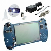
... Resource CD ■ Inspect the contents of the kit; if you do not find any part, contact your nearest Cypress sales office for help. CY8CKIT-006 PSoC 3 LCD Segment Drive Evaluation Kit Guide, Doc. # 001-52798 Rev. *C ® 3 LCD Segment Drive Evaluation Kit (EVK). ® 3 family of devices. ...
Page 6
... This guide uses the Courier New font to distinguish file names and file location from regular text. The keyboard commands and window selections are given in bold text. 6 CY8CKIT-006 PSoC 3 LCD Segment Drive Evaluation Kit Guide, Doc. # 001-52798 Rev. *C for additional learning resources in the form of data sheets, technical PDF Creation ...
Page 7
... Ensure that switch SW1 is in the OFF position prior to adding or removing batteries. 2. Insert a battery into the appropriate terminals or connect a wall transformer to the J2 jack. 3. Slide SW1 to the ON position if using a battery. The wall transformer supply is not controlled by SW1 and is always ON. CY8CKIT-006 PSoC 3 LCD Segment Drive Evaluation Kit Guide, Doc. # 001-52798 Rev [+] Feedback ...
Page 8
... CY8CKIT-006 PSoC 3 LCD Segment Drive Evaluation Kit PSoC Creator IDE ■ PSoC Programmer 3.10 ■ ■ Example Project at C:\Program Files\Cypress\CY8CKIT-006_PSoC3_LCD_Drive_Kit\1.0\Firmware Documents at ■ C:\Program Files\Cypress\CY8CKIT-006_PSoC3_LCD_Drive_Kit\1.0\Documenta- tion Schematic design files at: ■ C:\Program Files\Cypress\CY8CKIT-006_PSoC3_LCD_Drive_Kit\1.0\Hardware 8 CY8CKIT-006 PSoC 3 LCD Segment Drive Evaluation Kit Guide, Doc. # 001-52798 Rev. *C [+] Feedback ...
Page 9
... Kit Operation 3.1 Introduction The CY8CKIT-006 PSoC 3 LCD Segment Drive EVK firmware provides examples using a display with many segments (16 common lines by 28 segment lines giving 448 addressable segments). Figure 3-1. CY8CKIT-006 Kit 9V Battery Terminals Battery On/Off 9V-12V DC Power Jack Operator entries are made using the four CapSense buttons that are labeled: SEL, "+", "-", and RET. ...
Page 10
... An empty score has a 0G value in the test for lowest score. 10 CY8CKIT-006 PSoC 3 LCD Segment Drive Evaluation Kit Guide, Doc. # 001-52798 Rev. *C for more information on options to power the board. On startup, the kit Brief Description (1:GAUGE on page 10 section). By pressing the RET button, the Brief Description Record a punch acceleration ...
Page 11
... Punch menu (this also clears the RTC alarm settings and the RTC date). If you press RET, the project returns to the Punch menu without clearing the saved scores. CY8CKIT-006 PSoC 3 LCD Segment Drive Evaluation Kit Guide, Doc. # 001-52798 Rev. *C Kit Operation ...
Page 12
... Press "+" or "-" to select '0' - '5'. Press SEL to advance to the next M position (M2). ■ 12 CY8CKIT-006 PSoC 3 LCD Segment Drive Evaluation Kit Guide, Doc. # 001-52798 Rev. *C Brief Description Show time, date, and temperature Enter time of day Enter calendar date Enter alarm time of day ...
Page 13
... Press SEL to advance to the next H position (H2). ■ Press "+" or "-" to select ' '0' or '0' -' '1'. ■ Press SEL to advance to the left M position (M1). ■ Press "+" or "-" to select '0' - '5'. ■ CY8CKIT-006 PSoC 3 LCD Segment Drive Evaluation Kit Guide, Doc. # 001-52798 Rev. *C Kit Operation 13 [+] Feedback ...
Page 14
... The progress bar at the bottom displays the contrast level in graphical format. Pressing SEL or RET stores the contrast level in the persistent memory and project returns to the CONTRAST sub menu. 14 CY8CKIT-006 PSoC 3 LCD Segment Drive Evaluation Kit Guide, Doc. # 001-52798 Rev. *C [+] Feedback ...
Page 15
... C:\Program Files\Cypress\CY8CKIT-006_PSoC_3_LCD_Drive_Kit\ 1.0\Firmware\SegLCD_project\SegLCD_project.cydsn\DP8051-Keil_Generic\ Debug\SegLCD_project.hex Note The MiniProg3 version numbers may be higher numbers based on release. You should include these version numbers in any request for assistance from Cypress Semiconductor. CY8CKIT-006 PSoC 3 LCD Segment Drive Evaluation Kit Guide, Doc. # 001-52798 Rev. *C Figure 3-2. Kit Operation 15 ...
Page 16
... Select File > Program to download the kit project to the PSoC 3 silicon. 9. When the program is successfully downloaded, a "Programming Succeeded" message is dis- played in the programmer window as shown in 10.Rest the device by plugging out and plugging in the power to the board 16 CY8CKIT-006 PSoC 3 LCD Segment Drive Evaluation Kit Guide, Doc. # 001-52798 Rev. *C Figure 3-3. Figure 3-3. ...
Page 17
... Figure 3-3. Program Download Succeeded 3.8 Example Projects Refer to Application Note AN52927, LCD Direct Drive Basics, for steps to create a simple example project with this kit. CY8CKIT-006 PSoC 3 LCD Segment Drive Evaluation Kit Guide, Doc. # 001-52798 Rev. *C Kit Operation 17 [+] Feedback ...
Page 18
... Kit Operation 18 CY8CKIT-006 PSoC 3 LCD Segment Drive Evaluation Kit Guide, Doc. # 001-52798 Rev. *C [+] Feedback ...
Page 19
... PSoC's superior ability to integrate high performance digital and analog peripherals by integrating the accelerometer, thermistor, Real Time Clock, CapSense, and buzzer. Refer to Functional Description on page 21 applications. CY8CKIT-006 PSoC 3 LCD Segment Drive Evaluation Kit Guide, Doc. # 001-52798 Rev know about functional implementation of the 19 [+] Feedback ...
Page 20
... JTAG MiniProg3 Connector 10 (J1) 20 CY8CKIT-006 PSoC 3 LCD Segment Drive Evaluation Kit Guide, Doc. # 001-52798 Rev. *C Description This switch turns the power supplied by the battery On and Off. Note Switch (SW1) does not control the power supplied by sources through J1(USB) and J2(Wall Power). ...
Page 21
... AM/PM Alarm Indicator G Cypress Logo H Large Seven - Segment Display Area J 16/14 Segment Display Area K Signal Strength Bars L Progress Bars M Battery Level Bars CY8CKIT-006 PSoC 3 LCD Segment Drive Evaluation Kit Guide, Doc. # 001-52798 Rev. *C Table 4-1 lists the segments details. Description Hardware 21 [+] Feedback ...
Page 22
... Power Supply Options The kit can be powered by only one of the three voltage sources. Sl. No. Description 1 Battery 2 Wall Power 3 USB Power 22 CY8CKIT-006 PSoC 3 LCD Segment Drive Evaluation Kit Guide, Doc. # 001-52798 Rev. *C 73. Typical Voltage Connection 9V BH3, BH4 9V to 12V J2 (100 mA minimum ...
Page 23
... Punch Meter Welcome Screen PUNCH LCD Demo LCD DEMO Contrast Control CONTRAST Time-Temp RTC/TEMP CY8CKIT-006 PSoC 3 LCD Segment Drive Evaluation Kit Guide, Doc. # 001-52798 Rev. *C Punch Meter Punch Meter Acceleration Save Measurements Measurement LCD Demo LCD Demo Character Demo All Segments Demos ...
Page 24
... Thermistor signal voltage ❐ Accelerometer Y-axis ❐ Accelerometer X-axis ❐ ❐ Battery level - 9V Battery level - AA ❐ Analog mux (AMUX): 6 input ■ VDAC to generate reference voltage for thermistor ■ 24 CY8CKIT-006 PSoC 3 LCD Segment Drive Evaluation Kit Guide, Doc. # 001-52798 Rev. *C [+] Feedback ...
Page 25
... Wake from sleep ❐ Wall Supply (Vin) Detect - regulated supply input voltage detect VBus Detect - USB VBus supply input voltage detect ❐ Digital Output: ■ Accelerator ON - firmware control ❐ CY8CKIT-006 PSoC 3 LCD Segment Drive Evaluation Kit Guide, Doc. # 001-52798 Rev. *C Firmware 25 [+] Feedback ...
Page 26
... The same equation, when converted to Celsius scale is as follows 273.15; where Tc is temperature in degree Celsius. The PSoC can measure the voltage across the thermistor but not the resistance value. 26 CY8CKIT-006 PSoC 3 LCD Segment Drive Evaluation Kit Guide, Doc. # 001-52798 Rev. *C [+] Feedback ...
Page 27
... Show Time sub mode, the code simply loops on CapSense button scans and reads and dis- plays the instantaneous time and date information. The temperature at the board thermistor is sam- CY8CKIT-006 PSoC 3 LCD Segment Drive Evaluation Kit Guide, Doc. # 001-52798 Rev. *C Firmware Figure 5-3 ...
Page 28
... High Impedance Analog. The default Built-In settings are used. Figure 5-4. Thermistor Reference Analog Port Configuration: General Tab 28 CY8CKIT-006 PSoC 3 LCD Segment Drive Evaluation Kit Guide, Doc. # 001-52798 Rev. *C Figure 5-64 to know the details of sequence in which various sections of ...
Page 29
... The input is configured for 1-pin width mapping and Hi-Z Analog during Power-On Reset. The port pin is set for High Impedance Analog. The default Built-In settings are used. Figure 5-6. Thermistor Signal Analog Port Configuration: General Tab CY8CKIT-006 PSoC 3 LCD Segment Drive Evaluation Kit Guide, Doc. # 001-52798 Rev. *C Firmware 29 ...
Page 30
... The input is configured for 1-pin width mapping and Hi-Z Analog during Power-On Reset. The port pin is set for High Impedance Analog. The default Built-In settings are used. Figure 5-8. Accelerometer Y-Axis Analog Port Configuration: General Tab 30 CY8CKIT-006 PSoC 3 LCD Segment Drive Evaluation Kit Guide, Doc. # 001-52798 Rev. *C [+] Feedback ...
Page 31
... The input is configured for 1-pin width mapping and Hi-Z Analog during Power-On Reset. The port pin is set for High Impedance Analog. The default Built-In settings are used. Figure 5-10. Accelerometer X-Axis Analog Port Configuration: General Tab CY8CKIT-006 PSoC 3 LCD Segment Drive Evaluation Kit Guide, Doc. # 001-52798 Rev. *C Firmware 31 ...
Page 32
... AMUX to be sampled by the Delta-Sigma ADC during sampling periods. TThe input is configured for 1-pin width mapping and Hi-Z Analog during Power-On Reset. The port pin is set for High Imped- ance Analog. The default Built-In settings are used. 32 CY8CKIT-006 PSoC 3 LCD Segment Drive Evaluation Kit Guide, Doc. # 001-52798 Rev. *C [+] Feedback ...
Page 33
... Figure 5-12. Battery Monitor - 9V Level: General Tab Figure 5-13. Battery Monitor - 9V Level: Pin Type Tab CY8CKIT-006 PSoC 3 LCD Segment Drive Evaluation Kit Guide, Doc. # 001-52798 Rev. *C Firmware 33 [+] Feedback ...
Page 34
... The project code calls the VDAC SetRange API to select the 4V range and the SetValue API to set the output voltage at value=250. This sets the thermistor reference level at just under 4V to allow operation at Vdda as low as 4V. The VDAC is turned off between thermistor measurements to save power. 34 CY8CKIT-006 PSoC 3 LCD Segment Drive Evaluation Kit Guide, Doc. # 001-52798 Rev. *C [+] Feedback ...
Page 35
... The default Built-In settings are used. Figure 5-16. ADC Configuration CY8CKIT-006 PSoC 3 LCD Segment Drive Evaluation Kit Guide, Doc. # 001-52798 Rev. *C Firmware 35 [+] Feedback ...
Page 36
... The design uses a simple 50% duty cycle signal and does not require a high resolution. The default Built-In settings are used. Figure 5-17. PWM Configuration: Configure Tab Figure 5-18. PWM Configuration: Advanced Tab 36 CY8CKIT-006 PSoC 3 LCD Segment Drive Evaluation Kit Guide, Doc. # 001-52798 Rev. *C [+] Feedback ...
Page 37
... The PWM requires a clock source to create the output frequency. The default Built-In settings are used. Figure 5-19. PWM Clock Source Configuration Figure 5-20. PWM Clock Source Configuration: Advanced Tab CY8CKIT-006 PSoC 3 LCD Segment Drive Evaluation Kit Guide, Doc. # 001-52798 Rev. *C Firmware 37 [+] Feedback ...
Page 38
... An activity timer to automatically signal enter sleep after a period of no button presses. ■ ■ A data entry blink timer to provide blinking of characters as they are prompted for entry). The default Built-In settings are used. Figure 5-21. Timer Configuration 38 CY8CKIT-006 PSoC 3 LCD Segment Drive Evaluation Kit Guide, Doc. # 001-52798 Rev. *C [+] Feedback ...
Page 39
... The timer requires a clock source to create the output frequency. The default Built-In settings are used. Figure 5-22. Timer Clock Source Configuration Figure 5-23. Timer Clock Source Configuration: Advanced CY8CKIT-006 PSoC 3 LCD Segment Drive Evaluation Kit Guide, Doc. # 001-52798 Rev. *C Firmware 39 [+] Feedback ...
Page 40
... ISR code to decrement that count variable. Code is also added for the logic to be executed when the count variable reaches zero. Figure 5-24. Timer ISR Default Built-In Configuration 40 CY8CKIT-006 PSoC 3 LCD Segment Drive Evaluation Kit Guide, Doc. # 001-52798 Rev. *C [+] Feedback ...
Page 41
... The glass is of type FSTN with a 6 o'clock viewing angle. The drive method is 1/16 Duty, 1/5 Bias. The operating voltage is 3.3V. The polarizer mode is Reflective/Positive. Figure 5-25. Segment LCD Configuration: Basic Tab CY8CKIT-006 PSoC 3 LCD Segment Drive Evaluation Kit Guide, Doc. # 001-52798 Rev. *C CONTRAST on page 14). The frame rate is ...
Page 42
... The 16-segment character is mapped with the H16SEG0… symbols and the 14-character is mapped with the H14SEG0… symbols. 42 CY8CKIT-006 PSoC 3 LCD Segment Drive Evaluation Kit Guide, Doc. # 001-52798 Rev. *C [+] Feedback ...
Page 43
... Figure 5-27. Pixel Mapping Dialog: Matrix Helper CY8CKIT-006 PSoC 3 LCD Segment Drive Evaluation Kit Guide, Doc. # 001-52798 Rev. *C Firmware 43 [+] Feedback ...
Page 44
... Firmware Figure 5-28. Five Character Helper for Large Seven Segment Display Figure 5-29. Four Character Helper for Small Seven Segment Display 44 CY8CKIT-006 PSoC 3 LCD Segment Drive Evaluation Kit Guide, Doc. # 001-52798 Rev. *C [+] Feedback ...
Page 45
... Figure 5-30. One Character Helper for 16-Segment Display Figure 5-31. One Character Helper for 14-Segment Display CY8CKIT-006 PSoC 3 LCD Segment Drive Evaluation Kit Guide, Doc. # 001-52798 Rev. *C Firmware 45 [+] Feedback ...
Page 46
... API calls for the bar graph. Figure 5-32. Bar Graph Helper for 10-Element Progress Bar Icons 46 CY8CKIT-006 PSoC 3 LCD Segment Drive Evaluation Kit Guide, Doc. # 001-52798 Rev. *C [+] Feedback ...
Page 47
... Figure 5-34. Bar Graph Helper for Four Element Battery Level Icons It includes remaining icon pixels: four large decimal points, large colon, slash, bell, MAX, AM, PM, small decimal points, and small colon). CY8CKIT-006 PSoC 3 LCD Segment Drive Evaluation Kit Guide, Doc. # 001-52798 Rev. *C Firmware 47 ...
Page 48
... Power Entry on page 64. When the project is powered from a wall supply and the operator is in the RTC/TEMP submenu, then the sleep entry is blocked. If the project is battery powered, there is no sleep blocking. 48 CY8CKIT-006 PSoC 3 LCD Segment Drive Evaluation Kit Guide, Doc. # 001-52798 Rev. *C Low [+] Feedback ...
Page 49
... Figure 5-35. Sleep Button Configuration: General Tab Figure 5-36. Sleep Button Configuration: Pin Type Tab (includes dual-edge interrupt configuration) CY8CKIT-006 PSoC 3 LCD Segment Drive Evaluation Kit Guide, Doc. # 001-52798 Rev. *C Firmware 49 [+] Feedback ...
Page 50
... The code added is a prototype for the user provided ISR and a call to the user ISR in the generated source. 50 CY8CKIT-006 PSoC 3 LCD Segment Drive Evaluation Kit Guide, Doc. # 001-52798 Rev. *C [+] Feedback ...
Page 51
... This signal is used in conjunction with the battery sense pins to communicate the current power con- figuration to the project. The default Built-In settings are used. Figure 5-39. Wall Supply (Vin) Detect Configuration: General Tab CY8CKIT-006 PSoC 3 LCD Segment Drive Evaluation Kit Guide, Doc. # 001-52798 Rev. *C Firmware 51 ...
Page 52
... Firmware Figure 5-40. Wall Supply (Vin) Detect Configuration: Pin Type Tab Figure 5-41. Wall Supply (Vin) Detect Configuration Input Tab 52 CY8CKIT-006 PSoC 3 LCD Segment Drive Evaluation Kit Guide, Doc. # 001-52798 Rev. *C [+] Feedback ...
Page 53
... Detect signal is used in conjunction with the battery sense pins to help communicate the current power configuration to the project. The default Built-In settings are used. Figure 5-42. VBus Detect Configuration: General Tab Figure 5-43. VBus Detect Configuration: Pin Type Tab CY8CKIT-006 PSoC 3 LCD Segment Drive Evaluation Kit Guide, Doc. # 001-52798 Rev. *C Firmware 53 [+] Feedback ...
Page 54
... The firmware uses API to write to this port to turn on the accelerometer, enabling measurements. The default Built-In settings are used. Figure 5-44. Accelerometer On Configuration: General Tab Figure 5-45. Accelerometer On Configuration: Pin Type Tab 54 CY8CKIT-006 PSoC 3 LCD Segment Drive Evaluation Kit Guide, Doc. # 001-52798 Rev. *C [+] Feedback ...
Page 55
... PWM to the digital port for output mapping. The default Built-In settings are used. Figure 5-47. Buzzer In Configuration: General Tab CY8CKIT-006 PSoC 3 LCD Segment Drive Evaluation Kit Guide, Doc. # 001-52798 Rev. *C Firmware 55 ...
Page 56
... Figure 5-48. Buzzer In Configuration: Pin Type Tab Figure 5-49. Buzzer In Configuration: Output Tab 5.3.9.8 Logic Level High for Buzzer In Output Enable The Buzzer In digital output component requires a signal on the OE pin to enable the output. 56 CY8CKIT-006 PSoC 3 LCD Segment Drive Evaluation Kit Guide, Doc. # 001-52798 Rev. *C [+] Feedback ...
Page 57
... The Timer user ISR can be enhanced to provided button sense events. Note The CapSense CPS clock must not be greater than one half the projects bus clock selection (see System Clocks on page CY8CKIT-006 PSoC 3 LCD Segment Drive Evaluation Kit Guide, Doc. # 001-52798 Rev. *C 61). Firmware 57 [+] Feedback ...
Page 58
... Firmware Figure 5-51. CapSense Configuration: General Tab Figure 5-52. CapSense Configuration: Clock Source Tab 58 CY8CKIT-006 PSoC 3 LCD Segment Drive Evaluation Kit Guide, Doc. # 001-52798 Rev. *C [+] Feedback ...
Page 59
... Figure 5-53. CapSense Configuration: Buttons Tab Figure 5-54. CapSense Configuration: Scan Slots Tab CY8CKIT-006 PSoC 3 LCD Segment Drive Evaluation Kit Guide, Doc. # 001-52798 Rev. *C Firmware 59 [+] Feedback ...
Page 60
... Month Index, Year) 13 Clock Alarm OFF/ON Clock Time 14 (Hour, Minute) 60 CY8CKIT-006 PSoC 3 LCD Segment Drive Evaluation Kit Guide, Doc. # 001-52798 Rev. *C Description Initialization String – if this string is missing then automatically re-initialize the EEPROM project data Name is String Score is Long Name is String ...
Page 61
... These clocks are enabled in the Configure Built In Clocks dialog. To get to this dialog, select SegLCD_project.cydwr in the Workspace Explorer. Select the Clocks tab at the bottom of the workspace and then click Edit Clock on top of the workspace. CY8CKIT-006 PSoC 3 LCD Segment Drive Evaluation Kit Guide, Doc. # 001-52798 Rev. *C Firmware 61 ...
Page 62
... PSoC3 block in the center panel. To remove a connection, right click the assigned target pin stub and unlock the signal name. 62 CY8CKIT-006 PSoC 3 LCD Segment Drive Evaluation Kit Guide, Doc. # 001-52798 Rev. *C [+] Feedback ...
Page 63
... Figure 5-57. Pin Connection Mapping Page 1 CY8CKIT-006 PSoC 3 LCD Segment Drive Evaluation Kit Guide, Doc. # 001-52798 Rev. *C Firmware 63 [+] Feedback ...
Page 64
... Set 32 kHz clock to low power mode (API call). 2. Set trim registers (sleep and wake trims). 3. Stop timer components (except RTC). 4. Disable component clocks. 5. Deactivate accelerometer. 6. Deactivate thermistor VDAC reference generator. 64 CY8CKIT-006 PSoC 3 LCD Segment Drive Evaluation Kit Guide, Doc. # 001-52798 Rev. *C [+] Feedback ...
Page 65
... The following tasks must be performed after waking from low power to continue normal operations: 1. Set segment LCD to low power mode (API call). 2. Restart CapSense. 3. Reactivate component clocks. 4. Restart timer components. 5. Restart ADC component. CY8CKIT-006 PSoC 3 LCD Segment Drive Evaluation Kit Guide, Doc. # 001-52798 Rev. *C Firmware 65 [+] Feedback ...
Page 66
... SEL button while that mode name is displayed. On selecting a mode of operation, the main process transfers control to a sub mode control level with sub mode menus and controls. Figure 5-59. Main Code Flow 66 CY8CKIT-006 PSoC 3 LCD Segment Drive Evaluation Kit Guide, Doc. # 001-52798 Rev. *C [+] Feedback ...
Page 67
... SEL while that sub mode name is displayed. Pressing RET, exits the Punch Gauge sub mode and re-enters the Main Flow. All the Punch processes display characters on the matrix display. Figure 5-60. Punch Code Flow CY8CKIT-006 PSoC 3 LCD Segment Drive Evaluation Kit Guide, Doc. # 001-52798 Rev. *C Firmware 67 [+] Feedback ...
Page 68
... SEL button while that sub mode name is displayed. Upon selecting a sub mode operation, the Time/Temperature mode transfers control to a sub mode control level with sub mode menus and controls. Figure 5-61. RTC Code Flow 68 CY8CKIT-006 PSoC 3 LCD Segment Drive Evaluation Kit Guide, Doc. # 001-52798 Rev. *C Figure 5-62 shows the Date/Temperature code flow. On [+] Feedback ...
Page 69
... Figure 5-62. Clock Show Time and Date/Temperature Flow CY8CKIT-006 PSoC 3 LCD Segment Drive Evaluation Kit Guide, Doc. # 001-52798 Rev. *C Firmware 69 [+] Feedback ...
Page 70
... The Progress Bar icons are turned on from left to right to display the contrast level. The "+' and "-" buttons control the increment and decrement of the contrast level. Figure 5-63. Contrast Control Flow 70 CY8CKIT-006 PSoC 3 LCD Segment Drive Evaluation Kit Guide, Doc. # 001-52798 Rev. *C [+] Feedback ...
Page 71
... LCD Demonstration Mode Figure 5-64. LCD Demonstration Code Flow CY8CKIT-006 PSoC 3 LCD Segment Drive Evaluation Kit Guide, Doc. # 001-52798 Rev. *C Firmware 71 [+] Feedback ...
Page 72
... All other register activity is performed by the com- ponent the API calls. Table 5-2. Register Descriptions Register Component Name CYDEV_MFGCFG_P WRSYS_SLP_TR CYDEV_MFGCFG_P WRSYS_WAKE_TR0 CYDEV_MFGCFG_P WRSYS_WAKE_TR1 72 CY8CKIT-006 PSoC 3 LCD Segment Drive Evaluation Kit Guide, Doc. # 001-52798 Rev. *C Register Silicon Register Write Name Address Value PWR- 0x4683 0x03 SYS.SLP_TR PWR- ...
Page 73
... A. Appendix A.1 Pixel Mapping Table for LCD Glass CY8CKIT-006 PSoC 3 LCD Segment Drive Evaluation Kit Guide, Doc. # 001-52798 Rev [+] Feedback ...
Page 74
... A.2 Segment Lettering Information 74 CY8CKIT-006 PSoC 3 LCD Segment Drive Evaluation Kit Guide, Doc. # 001-52798 Rev. *C [+] Feedback ...
Page 75
... A.3 Schematic CY8CKIT-006 PSoC 3 LCD Segment Drive Evaluation Kit Guide, Doc. # 001-52798 Rev [+] Feedback ...
Page 76
... SMA CONN HEADER 10 PIN 50MIL KEYED SMD CONN JACK POWER 2.1mm PCB RA 76 CY8CKIT-006 PSoC 3 LCD Segment Drive Evaluation Kit Guide, Doc. # 001-52798 Rev. *C Part Manufacturer Keystone Elec- tronics Keystone Elec- tronics Kemet Kemet AVX Murata Electron- ics North Amer- ...
Page 77
... R46 RES 62K OHM 1/10W 5% 0402 SMD 32 3 R49,R50,R5 RES 0.0 OHM 1/10W 5% 9 0805 SMD CY8CKIT-006 PSoC 3 LCD Segment Drive Evaluation Kit Guide, Doc. # 001-52798 Rev. *C Part Manufacturer Molex/Waldom Electronics Corp CUI Inc FEMA BC Components Yageo Corpora- tion Panasonic - ECG ...
Page 78
... D12 DIODE SCHOTTKY 40V 1.5A SMA 49 1 D10 Diode, Zener, 3W, 5.6V, SMB 78 CY8CKIT-006 PSoC 3 LCD Segment Drive Evaluation Kit Guide, Doc. # 001-52798 Rev. *C Part Manufacturer ITT Industries, C&K Div Panasonic - ECG Keystone Elec- tronics Keystone Elec- tronics Cypress Semi- conductor ...
Page 79
... TEST POINT 43 HOLE 65 PLATED BLACK Install On Bottom of PCB Near Rounded Corners As Noted On SASSY assembly drawing n/a BUMPER CLEAR.370X.19" CYLIN- DER CY8CKIT-006 PSoC 3 LCD Segment Drive Evaluation Kit Guide, Doc. # 001-52798 Rev. *C Part Manufacturer TYCO Panasonic - ECG TDK Corporation Keystone Elec- tronics Panasonic - ECG ...
Page 80
... A.5 PCB Layout and Silkscreen 80 CY8CKIT-006 PSoC 3 LCD Segment Drive Evaluation Kit Guide, Doc. # 001-52798 Rev. *C [+] Feedback ...