CY8CKIT-006 Cypress Semiconductor Corp, CY8CKIT-006 Datasheet - Page 26
CY8CKIT-006
Manufacturer Part Number
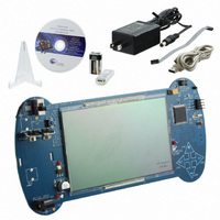
CY8CKIT-006
Description
KIT DEV PSOC3 LCD SEGMENT
Manufacturer
Cypress Semiconductor Corp
Series
PSOC™ 3r
Specifications of CY8CKIT-006
Main Purpose
Displays, LCD Display
Embedded
Yes, MCU, 32-Bit
Primary Attributes
448 addressable segments
Secondary Attributes
Configurable LCD pin selection
Description/function
Evaluation Kit
Interface Type
USB
Backlighting
No Backlighting
Data Bus Width
8 bit, 16 bit, 32 bit
Maximum Operating Temperature
+ 50 C
Minimum Operating Temperature
0 C
Number Of Segments
7
Operating Supply Voltage
12 V
Operating Voltage
3.3 V
Pixel Format
16 x 28
Product
Display Modules
Software
Software Included
Touch Panel
No Touch Panel
For Use With/related Products
PSoC 3
Lead Free Status / RoHS Status
Lead free / RoHS Compliant
Utilized Ic / Part
-
Lead Free Status / Rohs Status
Lead free / RoHS Compliant
Other names
428-2994
Available stocks
Company
Part Number
Manufacturer
Quantity
Price
Company:

Part Number:
CY8CKIT-006
Manufacturer:
Cypress Semiconductor Corp
Quantity:
135


Firmware
5.2
5.2.1
5.2.1.1
5.2.1.2
5.2.2
26
■
■
■
Application Descriptions
Punch Gauge Accelerometer Algorithm
The Punch Gauge code runs a peak and hold algorithm in a tight loop continuously updating until
there is a change in the program state. Both the X and Y-axis accelerometer outputs are sampled
separately and continuously. The higher of the two axis measurements is reported as the score.
At Rest Peak and Hold
When the operator initiates a Punch Gauge punch, the punch code begins reading the instanta-
neous X and Y-axis accelerometer outputs for a period of three seconds. This is to measure maxi-
mum at rest acceleration that the board experiences. This is saved as a baseline for the punch
measurement.
Punch Peak and Hold
After the Punch Gauge has stored the baseline at rest acceleration, the punch code begins continu-
ously sampling both the X and Y-axis accelerometer outputs. The code continues to sample and hold
the peak values until the operator terminates the operation by pressing SEL button. During this sam-
pling period the operator "throws" a punch or punches. The algorithm continues to peak and hold
until the operator presses SEL button.
When the SEL button is pressed, the punch code subtracts the at rest X-axis baseline reading from
the punch X-axis peak reading and subtracts the at rest Y-axis baseline from the punch Y-axis peak
reading. The greater of the X and Y-axis results is reported as the punch acceleration.
Temperature Measurements
The temperature sensing demonstration shows how the PSoC is used to sense temperature using a
thermistor. The thermistor resistance varies with temperature following a predictable non-linear
curve. The temperature-resistance relationship is given by the Steinhart-Hart equation:
1 /Tk = A + B.ln(R) + C.(ln(R))3
Where:
■
■
■
The same equation, when converted to Celsius scale is as follows:
Tc = Tk - 273.15; where Tc is temperature in degree Celsius.
The PSoC can measure the voltage across the thermistor but not the resistance value.
❐
Logic level High for Buzzer OE
RTC: Enable 32.768 RTC clock
CapSense:
❐
❐
EEPROM: Persistent memory storage (saved scores, contrast level, clock settings)
A, B, and C are empirical constants known as Steinhart-Hart coefficients
R is the resistance of the thermistor in Ohms
Tk is the temperature in degree Kelvins
Buzzer - hardware control
CMod connection
RBleed connection
CY8CKIT-006 PSoC 3 LCD Segment Drive Evaluation Kit Guide, Doc. # 001-52798 Rev. *C
[+] Feedback
Related parts for CY8CKIT-006
Image
Part Number
Description
Manufacturer
Datasheet
Request
R

Part Number:
Description:
KIT DEV FOR PSOC3/5
Manufacturer:
Cypress Semiconductor Corp
Datasheet:

Part Number:
Description:
PSoC1/3/5 Development Kit
Manufacturer:
Cypress Semiconductor Corp
Datasheet:

Part Number:
Description:
KIT DEV PSOC PROC MODULE CY8C38
Manufacturer:
Cypress Semiconductor Corp

Part Number:
Description:
KIT DEV PSOC PROC MODULE CY8C29
Manufacturer:
Cypress Semiconductor Corp

Part Number:
Description:
KIT DEV PSOC ANALOG VOLTMETER
Manufacturer:
Cypress Semiconductor Corp
Datasheet:

Part Number:
Description:
KIT DEV PSOC5 FIRST TOUCH
Manufacturer:
Cypress Semiconductor Corp
Datasheet:

Part Number:
Description:
KIT DEV PSOC3 FIRSTTOUCH STARTER
Manufacturer:
Cypress Semiconductor Corp
Datasheet:
Part Number:
Description:
KIT DEV PROC MODULE PSOC5
Manufacturer:
Cypress Semiconductor Corp
Datasheet:

Part Number:
Description:
KIT PSOC CY8C28 FAMILY PROCESSOR
Manufacturer:
Cypress Semiconductor Corp
Datasheet:

Part Number:
Description:
KIT PSOC MINIPROG3 PROGRAM DEBUG
Manufacturer:
Cypress Semiconductor Corp
Datasheet:

Part Number:
Description:
KIT EVAL POWERLINE HIGH VOLT
Manufacturer:
Cypress Semiconductor Corp
Datasheet:

Part Number:
Description:
KIT PSOC FIRST TOUCH
Manufacturer:
Cypress Semiconductor Corp
Datasheet:

Part Number:
Description:
EVAL KIT WORLDTOUR2
Manufacturer:
Cypress Semiconductor Corp
Datasheet:

Part Number:
Description:
KIT UNIVERSAL CAPSENSE CTRLR
Manufacturer:
Cypress Semiconductor Corp
Datasheet:
