CY8CKIT-006 Cypress Semiconductor Corp, CY8CKIT-006 Datasheet - Page 40
CY8CKIT-006
Manufacturer Part Number
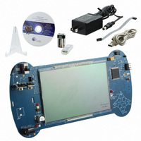
CY8CKIT-006
Description
KIT DEV PSOC3 LCD SEGMENT
Manufacturer
Cypress Semiconductor Corp
Series
PSOC™ 3r
Specifications of CY8CKIT-006
Main Purpose
Displays, LCD Display
Embedded
Yes, MCU, 32-Bit
Primary Attributes
448 addressable segments
Secondary Attributes
Configurable LCD pin selection
Description/function
Evaluation Kit
Interface Type
USB
Backlighting
No Backlighting
Data Bus Width
8 bit, 16 bit, 32 bit
Maximum Operating Temperature
+ 50 C
Minimum Operating Temperature
0 C
Number Of Segments
7
Operating Supply Voltage
12 V
Operating Voltage
3.3 V
Pixel Format
16 x 28
Product
Display Modules
Software
Software Included
Touch Panel
No Touch Panel
For Use With/related Products
PSoC 3
Lead Free Status / RoHS Status
Lead free / RoHS Compliant
Utilized Ic / Part
-
Lead Free Status / Rohs Status
Lead free / RoHS Compliant
Other names
428-2994
Available stocks
Company
Part Number
Manufacturer
Quantity
Price
Company:

Part Number:
CY8CKIT-006
Manufacturer:
Cypress Semiconductor Corp
Quantity:
135


Firmware
5.3.7.1
5.3.7.2
40
Logic Level Low for Timer
The timer component requires a signal on the Reset pin to keep it out of reset after power on reset.
The design does not require the application of a Reset signal on the timer during operation.
Timer ISR
The timer is implemented with the use of a Terminal Count (TC) interrupt. After adding the interrupt
to the tc-pin of the timer component, PSoC Creator generates source files for the interrupt service.
References to the project code interrupt service routine are added to the generated source. In the
generated source file for interrupt handling, there are two places where code must be added by
hand. This code is protected by source code generator statements that preserve the user added
code on subsequent builds. The code that is added is a prototype for the user provided interrupt ser-
vice routine and a call to the interrupt service routine (user ISR).
The Timer ISR is set for an interval of once every 100 ms. For a timeout period of 1s, the timer is ini-
tialized for a 10 count period.
The actual timer component is initialized at the start of the project. When a timing element is
required, a global cont variable is added to the timer user ISR code to decrement that count variable.
Code is also added for the logic to be executed when the count variable reaches zero.
Figure 5-24. Timer ISR Default Built-In Configuration
CY8CKIT-006 PSoC 3 LCD Segment Drive Evaluation Kit Guide, Doc. # 001-52798 Rev. *C
[+] Feedback
Related parts for CY8CKIT-006
Image
Part Number
Description
Manufacturer
Datasheet
Request
R

Part Number:
Description:
KIT DEV FOR PSOC3/5
Manufacturer:
Cypress Semiconductor Corp
Datasheet:

Part Number:
Description:
PSoC1/3/5 Development Kit
Manufacturer:
Cypress Semiconductor Corp
Datasheet:

Part Number:
Description:
KIT DEV PSOC PROC MODULE CY8C38
Manufacturer:
Cypress Semiconductor Corp

Part Number:
Description:
KIT DEV PSOC PROC MODULE CY8C29
Manufacturer:
Cypress Semiconductor Corp

Part Number:
Description:
KIT DEV PSOC ANALOG VOLTMETER
Manufacturer:
Cypress Semiconductor Corp
Datasheet:

Part Number:
Description:
KIT DEV PSOC5 FIRST TOUCH
Manufacturer:
Cypress Semiconductor Corp
Datasheet:

Part Number:
Description:
KIT DEV PSOC3 FIRSTTOUCH STARTER
Manufacturer:
Cypress Semiconductor Corp
Datasheet:
Part Number:
Description:
KIT DEV PROC MODULE PSOC5
Manufacturer:
Cypress Semiconductor Corp
Datasheet:

Part Number:
Description:
KIT PSOC CY8C28 FAMILY PROCESSOR
Manufacturer:
Cypress Semiconductor Corp
Datasheet:

Part Number:
Description:
KIT PSOC MINIPROG3 PROGRAM DEBUG
Manufacturer:
Cypress Semiconductor Corp
Datasheet:

Part Number:
Description:
KIT EVAL POWERLINE HIGH VOLT
Manufacturer:
Cypress Semiconductor Corp
Datasheet:

Part Number:
Description:
KIT PSOC FIRST TOUCH
Manufacturer:
Cypress Semiconductor Corp
Datasheet:

Part Number:
Description:
EVAL KIT WORLDTOUR2
Manufacturer:
Cypress Semiconductor Corp
Datasheet:

Part Number:
Description:
KIT UNIVERSAL CAPSENSE CTRLR
Manufacturer:
Cypress Semiconductor Corp
Datasheet:
