STEVAL-IFW001V1 STMicroelectronics, STEVAL-IFW001V1 Datasheet - Page 36
STEVAL-IFW001V1
Manufacturer Part Number
STEVAL-IFW001V1
Description
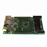
BOARD EVAL BASED ON STR912FA
Manufacturer
STMicroelectronics
Datasheets
1.STEVAL-IFW001V1.pdf
(102 pages)
2.STEVAL-IFW001V1.pdf
(9 pages)
3.STEVAL-IFW001V1.pdf
(7 pages)
Specifications of STEVAL-IFW001V1
Design Resources
STEVAL-IFW001V1 Gerber Files STEVAL-IFW001V1 Schematic STEVAL-IFW001V1 Bill of Material
Main Purpose
Interface, Ethernet
Embedded
Yes, MCU, 32-Bit
Utilized Ic / Part
E-STE101P, STR912FAW44
Primary Attributes
Dual Ethernet Transceivers for Full Duplex Communication
Secondary Attributes
Up to 32 MII Addresses, UART, I2C, SPI, with RJ45 Connectors
Silicon Manufacturer
ST Micro
Core Architecture
ARM
Core Sub-architecture
ARM9
Silicon Core Number
STR9
Silicon Family Name
STR91x
For Use With
497-8263 - BOARD EXTENSION STEVAL-IFW001V1
Lead Free Status / RoHS Status
Lead free / RoHS Compliant
Other names
497-8262


Functional overview
3.24.1
3.25
3.25.1
36/102
DMA
A programmable DMA channel may be assigned by CPU firmware to service each ADC
conversion result for fast DMA single-transfer.
Standard timers (TIM) with DMA
The STR91xFA has four independent, free-running 16-bit timer/counter modules designated
TIM0, TIM1, TIM2, and TIM3. Each general purpose timer/counter can be configured by
firmware for a variety of tasks including; pulse width and frequency measurement (input
capture), generation of waveforms (output compare and PWM), event counting, delay
timing, and up/down counting.
Each of the four timer units have the following features:
●
●
●
●
●
●
●
●
●
DMA
A programmable DMA channel may be assigned by CPU firmware to service each
timer/counter module TIM0 and TIM1 for fast and direct single transfers.
16-bit free running timer/counter
Internal timer/counter clock source from a programmable 8-bit prescale of the CCU
PCLK clock output
Optional external timer/counter clock source from pin P2.4 shared by TIM0/TIM1, and
pin P2.5 shared by TIM2/TIM3. Frequency of these external clocks must be at least 4
times less the frequency of the internal CCU PCLK clock output.
Two dedicated 16-bit Input Capture registers for measuring up to two input signals.
Input Capture has programmable selection of input signal edge detection
Two dedicated 16-bit Output Compare registers for generation up to two output signals
PWM output generation with 16-bit resolution of both pulse width and frequency
One pulse generation in response to an external event
A dedicated interrupt to the CPU with five interrupt flags
The OCF1 flag (Output Compare 1) from the timer can be configured to trigger an ADC
conversion
Doc ID 13495 Rev 6
STR91xFAxxx
Related parts for STEVAL-IFW001V1
Image
Part Number
Description
Manufacturer
Datasheet
Request
R

Part Number:
Description:
BOARD EVAL SPZB260 MOD FOR STR9
Manufacturer:
STMicroelectronics
Datasheet:

Part Number:
Description:
BOARD EVAL EXTENSION SN250
Manufacturer:
STMicroelectronics
Datasheet:

Part Number:
Description:
BOARD EVAL AB-54003L-512
Manufacturer:
STMicroelectronics
Datasheet:

Part Number:
Description:
BOARD REF DESIGN RF DMOS PWR AMP
Manufacturer:
STMicroelectronics
Datasheet:

Part Number:
Description:
BOARD EVAL PWR AMP AB-84008L-470
Manufacturer:
STMicroelectronics
Datasheet:

Part Number:
Description:
BOARD EVAL FOR STM32F103XX
Manufacturer:
STMicroelectronics
Datasheet:

Part Number:
Description:
BOARD EVAL AB-54003L-512
Manufacturer:
STMicroelectronics
Datasheet:

Part Number:
Description:
BOARD SMART PLUG STM32 SPZB260PR
Manufacturer:
STMicroelectronics
Datasheet:

Part Number:
Description:
BOARD DEMO BLUETOOTH SPBT2532C2
Manufacturer:
STMicroelectronics
Datasheet:
Part Number:
Description:
ZIGBEE USB DONGLE EVAL KIT
Manufacturer:
STMicroelectronics
Datasheet:
Part Number:
Description:
STMicroelectronics [RIPPLE-CARRY BINARY COUNTER/DIVIDERS]
Manufacturer:
STMicroelectronics
Datasheet:
Part Number:
Description:
STMicroelectronics [LIQUID-CRYSTAL DISPLAY DRIVERS]
Manufacturer:
STMicroelectronics
Datasheet:

Part Number:
Description:
BOARD EVAL FOR MEMS SENSORS
Manufacturer:
STMicroelectronics
Datasheet: