NCP1605FORWGEVB ON Semiconductor, NCP1605FORWGEVB Datasheet - Page 17
NCP1605FORWGEVB
Manufacturer Part Number
NCP1605FORWGEVB
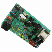
Description
EVAL BOARD FOR NCP1605FORWG
Manufacturer
ON Semiconductor
Datasheets
1.NCP1217P100G.pdf
(19 pages)
2.NCP1605ADR2G.pdf
(32 pages)
3.NCP1605FORWGEVB.pdf
(2 pages)
4.NCP1605FORWGEVB.pdf
(20 pages)
Specifications of NCP1605FORWGEVB
Design Resources
NCP1605FORWGEVB BOM NCP1605FORWGEVB Gerber Files NCP1605 EVB Schematic
Main Purpose
AC/DC, Primary and Secondary Side with PFC
Outputs And Type
1, Isolated
Voltage - Output
19V
Current - Output
8A
Voltage - Input
90 ~ 265VAC
Regulator Topology
Forward Converter
Frequency - Switching
133kHz
Board Type
Fully Populated
Utilized Ic / Part
NCP1217, NCP1605
Lead Free Status / RoHS Status
Lead free / RoHS Compliant
Power - Output
-
Lead Free Status / Rohs Status
Lead free / RoHS Compliant
For Use With/related Products
NCP1605FORWG
Other names
NCP1605FORWGEVBOS


Introduction
fixed frequency, Discontinuous Conduction Mode (DCM). In
the most stressful conditions, Critical Conduction Mode
(CRM) can be achieved without power factor degradation and
the circuit could be viewed as a CRM controller with a
frequency clamp (given by the oscillator). Finally, the
NCP1605(A) tends to give the best of both modes without
their respective drawbacks. Furthermore, the circuit
incorporates protection features for a rugged operation
together with some special circuitry to lower the power
consumed by the PFC stage in no load conditions. More
generally, the NCP1605(A) functions make it the ideal
candidate in systems where cost−effectiveness, reliability,
low standby power and high power factor are the key
parameters:
•
In all cases, the circuit provides near−unity power factor.
other applications, the circuit targets power supply where
the PFC stage must keep alive even in standby. A
continuous flow of pulses is not compatible with no−load
standby power requirements. Instead, the controller slices
the switching pattern in bunch of pulses to drastically
reduce the overall losses. The skip cycle operation is
initiated by applying to Pin 1, a signal that goes below
300 mV in standby. Typically, this signal is drawn from the
feedback of the downstream converter.
meeting low standby power specifications represents a
difficult exercise when the controller requires an external,
lossy resistor connected to the bulk capacitor. The
controller disables the high−voltage current source after
startup which no longer hampers the consumption in
no−load situations. In addition, the large V
to 20 V after startup), highly eases the circuit biasing.
low bandwidth of the regulation block, the output voltage
of PFC stages may exhibit excessive over and undershoots
because of abrupt load or input voltage variations (e.g. at
startup). If the output voltage is too far from the regulation
level:
The NCP1605(A) is a PFC driver designed to operate in
Skip−cycle capability for low power standby: among
Startup Current Source and large V
Fast Line / Load Transient Compensation: given the
Compactness and Flexibility: the controller requires
few external components while offering a large variety
of functions. Depending on the selected coil and
oscillator frequency you select, the circuit can:
1. Mostly operate in CRM and use the oscillator as a
2. Mostly operate in fixed frequency mode and only
3. Permanently operate in fixed frequency mode
frequency clamp.
run in CRM at high load and low line.
DCM.
DETAILED OPERATING DESCRIPTION
CC
range (10 V
CC
range:
http://onsemi.com
17
situation or if on the contrary, it is in a startup or fault
condition. In the first case, Pin 12 is in high state and low
otherwise. Pin 12 serves to control the downstream
converter operation in response to the PFC state.
monitors the input and output voltages, the coil current and
the die temperature to protect the system from possible
over−stresses and make the PFC stage extremely robust and
reliable. In addition to the aforementioned OVP protection,
one can list:
incorporates a −0.5 A / +0.8 A gate driver to efficiently
drive most TO220 or TO247 power MOSFETs.
PFC OK: the circuit detects when the circuit is in normal
Safety Protections: the NCP1605(A) permanently
Output
− The NCP1605(A) disables the drive to stop
− The NCP1605(A) drastically speeds up the
− Maximum Current Limit and Zero Current
− Undervoltage Protection: the circuit turns off
− Brown−Out Detection: the circuit detects too
− Thermal Shutdown: an internal thermal
delivering power as long as the output voltage
exceeds the Overvoltage Protection (OVP) level.
regulation loop when the output voltage is below
95.5% of its regulation level. This function is
allowed only after the PFC stage has started up
not to eliminate the soft−start effect.
Detection: the circuit permanently senses the
coil current and immediately turns off the
power switch if it is higher than the set current
limit. It also prevents any turn on of the power
switch as long as some current flows through
the coil, to ensure operation in DCM. This
feature also protects the MOSFET from the
excessive stress that could result from the
large in−rush currents that occurs during the
startup phases.
when it detects that the output voltage goes
below 12% of the OVP level (typically). This
feature protects the PFC stage from starting
operation in case of too low ac line conditions
or in case of a failure in the OVP monitoring
network (e.g., bad connection).
low ac line conditions and stop operating in
this case. This protection protects the PFC
stage from the excessive stress that could
damage it in such conditions.
circuitry disables the circuit gate drive and then
keeps the power switch off when the junction
temperature exceeds 150°C typically. The circuit
resumes operation once the temperature drops
below about 100°C (50°C hysteresis).
Stage
Totem
Pole:
the
NCP1605(A)
Related parts for NCP1605FORWGEVB
Image
Part Number
Description
Manufacturer
Datasheet
Request
R

Part Number:
Description:
ON Semiconductor [VOLTAGE REGULATOR]
Manufacturer:
ON Semiconductor
Datasheet:
Part Number:
Description:
357-036-542-201 CARDEDGE 36POS DL .156 BLK LOPRO
Manufacturer:
ON Semiconductor
Datasheet:
Part Number:
Description:
357-036-542-201 CARDEDGE 36POS DL .156 BLK LOPRO
Manufacturer:
ON Semiconductor
Datasheet:
Part Number:
Description:
357-036-542-201 CARDEDGE 36POS DL .156 BLK LOPRO
Manufacturer:
ON Semiconductor
Datasheet:
Part Number:
Description:
357-036-542-201 CARDEDGE 36POS DL .156 BLK LOPRO
Manufacturer:
ON Semiconductor
Datasheet:
Part Number:
Description:
357-036-542-201 CARDEDGE 36POS DL .156 BLK LOPRO
Manufacturer:
ON Semiconductor
Datasheet:
Part Number:
Description:
357-036-542-201 CARDEDGE 36POS DL .156 BLK LOPRO
Manufacturer:
ON Semiconductor
Datasheet:
Part Number:
Description:
357-036-542-201 CARDEDGE 36POS DL .156 BLK LOPRO
Manufacturer:
ON Semiconductor
Datasheet:
Part Number:
Description:
357-036-542-201 CARDEDGE 36POS DL .156 BLK LOPRO
Manufacturer:
ON Semiconductor
Datasheet:
Part Number:
Description:
357-036-542-201 CARDEDGE 36POS DL .156 BLK LOPRO
Manufacturer:
ON Semiconductor
Datasheet:
Part Number:
Description:
357-036-542-201 CARDEDGE 36POS DL .156 BLK LOPRO
Manufacturer:
ON Semiconductor
Datasheet:
Part Number:
Description:
Manufacturer:
ON Semiconductor
Datasheet:
Part Number:
Description:
Manufacturer:
ON Semiconductor
Datasheet:
Part Number:
Description:
Manufacturer:
ON Semiconductor
Datasheet: