STEVAL-IFS003V1 STMicroelectronics, STEVAL-IFS003V1 Datasheet - Page 105
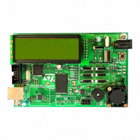
STEVAL-IFS003V1
Manufacturer Part Number
STEVAL-IFS003V1
Description
BOARD STLM75/STDS75/ST72F651
Manufacturer
STMicroelectronics
Datasheets
1.STLM75DS2F.pdf
(40 pages)
2.STDS75M2F.pdf
(39 pages)
3.STEVAL-IFS003V1.pdf
(161 pages)
4.STEVAL-IFS003V1.pdf
(4 pages)
Specifications of STEVAL-IFS003V1
Design Resources
STEVAL-IFS003V1 Gerber Files STEVAL-IFS003V1 Schematic STEVAL-IFS003V1 Bill of Materials
Sensor Type
Temperature
Sensing Range
-55°C ~ 125°C
Interface
I²C
Voltage - Supply
7.5 V ~ 19 V
Embedded
Yes, MCU, 8-Bit
Utilized Ic / Part
ST72F651, STDS75, STLM75
Silicon Manufacturer
ST Micro
Silicon Core Number
STLM75/STDS75 And ST72F651AR6
Kit Application Type
Sensing - Temperature
Application Sub Type
Temperature Sensor
Kit Contents
Board
Lead Free Status / RoHS Status
Lead free / RoHS Compliant
Sensitivity
-
Lead Free Status / Rohs Status
Lead free / RoHS Compliant
Other names
497-6238


11.7 I²C SINGLE MASTER BUS INTERFACE (I2C)
11.7.1 Introduction
The I
tween the microcontroller and the serial I
provides single master functions, and controls all
I
It supports fast I²C mode (400kHz).
11.7.2 Main Features
■
11.7.3 General Description
In addition to receiving and transmitting data, this
interface converts it from serial to parallel format
and vice versa, using either an interrupt or polled
handshake. The interrupts are enabled or disabled
by software. The interface is connected to the I
bus by a data pin (SDAI) and by a clock pin (SCLI).
It can be connected both with a standard I
Figure 62. I
2
C bus-specific sequencing, protocol and timing.
– Parallel bus /I
– Interrupt generation
– Standard I
– 7-bit Addressing
– End of byte transmission flag
– Transmitter/Receiver flag
– Clock generation
I
2
C single Master Mode
2
C Bus Interface serves as an interface be-
2
SCL
SDA
C BUS Protocol
2
C mode/Fast I
CONDITION
2
C protocol converter
START
2
C mode
MSB
1
2
C bus. It
2
2
Doc ID 7215 Rev 4
C bus
2
C
and a Fast I
ware.
Mode Selection
The interface can operate in the two following mo-
des:
– Master transmitter/receiver
By default, it is idle.
The interface automatically switches from idle to
master after it generates a START condition and
from master to idle after it generates a STOP
condition.
Communication Flow
The interface initiates a data transfer and genera-
tes the clock signal. A serial data transfer always
begins with a start condition and ends with a stop
condition. Both start and stop conditions are gene-
rated by software.
Data and addresses are transferred as 8-bit bytes,
MSB first. The first byte following the start condi-
tion is the address byte.
A 9th clock pulse follows the 8 clock cycles of a
byte transfer, during which the receiver must send
an acknowledge bit to the transmitter. Refer to
ure
62.
8
2
C bus. This selection is made by soft-
ACK
9
CONDITION
STOP
ST72651AR6
VR02119B
105/161
Fig-
Related parts for STEVAL-IFS003V1
Image
Part Number
Description
Manufacturer
Datasheet
Request
R

Part Number:
Description:
BOARD EVAL SPZB260 MOD FOR STR9
Manufacturer:
STMicroelectronics
Datasheet:

Part Number:
Description:
BOARD EVAL EXTENSION SN250
Manufacturer:
STMicroelectronics
Datasheet:

Part Number:
Description:
BOARD EVAL AB-54003L-512
Manufacturer:
STMicroelectronics
Datasheet:

Part Number:
Description:
BOARD REF DESIGN RF DMOS PWR AMP
Manufacturer:
STMicroelectronics
Datasheet:

Part Number:
Description:
BOARD EVAL PWR AMP AB-84008L-470
Manufacturer:
STMicroelectronics
Datasheet:

Part Number:
Description:
BOARD EVAL FOR STM32F103XX
Manufacturer:
STMicroelectronics
Datasheet:

Part Number:
Description:
BOARD EVAL AB-54003L-512
Manufacturer:
STMicroelectronics
Datasheet:

Part Number:
Description:
BOARD SMART PLUG STM32 SPZB260PR
Manufacturer:
STMicroelectronics
Datasheet:

Part Number:
Description:
BOARD DEMO BLUETOOTH SPBT2532C2
Manufacturer:
STMicroelectronics
Datasheet:
Part Number:
Description:
ZIGBEE USB DONGLE EVAL KIT
Manufacturer:
STMicroelectronics
Datasheet:
Part Number:
Description:
STMicroelectronics [RIPPLE-CARRY BINARY COUNTER/DIVIDERS]
Manufacturer:
STMicroelectronics
Datasheet:
Part Number:
Description:
STMicroelectronics [LIQUID-CRYSTAL DISPLAY DRIVERS]
Manufacturer:
STMicroelectronics
Datasheet:

Part Number:
Description:
BOARD EVAL FOR MEMS SENSORS
Manufacturer:
STMicroelectronics
Datasheet: