STEVAL-IFS003V1 STMicroelectronics, STEVAL-IFS003V1 Datasheet - Page 36
STEVAL-IFS003V1
Manufacturer Part Number
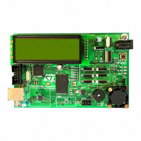
STEVAL-IFS003V1
Description
BOARD STLM75/STDS75/ST72F651
Manufacturer
STMicroelectronics
Datasheets
1.STLM75DS2F.pdf
(40 pages)
2.STDS75M2F.pdf
(39 pages)
3.STEVAL-IFS003V1.pdf
(161 pages)
4.STEVAL-IFS003V1.pdf
(4 pages)
Specifications of STEVAL-IFS003V1
Design Resources
STEVAL-IFS003V1 Gerber Files STEVAL-IFS003V1 Schematic STEVAL-IFS003V1 Bill of Materials
Sensor Type
Temperature
Sensing Range
-55°C ~ 125°C
Interface
I²C
Voltage - Supply
7.5 V ~ 19 V
Embedded
Yes, MCU, 8-Bit
Utilized Ic / Part
ST72F651, STDS75, STLM75
Silicon Manufacturer
ST Micro
Silicon Core Number
STLM75/STDS75 And ST72F651AR6
Kit Application Type
Sensing - Temperature
Application Sub Type
Temperature Sensor
Kit Contents
Board
Lead Free Status / RoHS Status
Lead free / RoHS Compliant
Sensitivity
-
Lead Free Status / Rohs Status
Lead free / RoHS Compliant
Other names
497-6238


ST72651AR6
POWER SUPPLY MANAGEMENT (Cont’d)
6.4.4 Register Description
POWER CONTROL REGISTER (PCR)
Reset Value: 0000 0000 (00h)
Bit 7 = ITPF Voltage Input Threshold Plus Flag
This bit is set by hardware when USBV
over USBV
BV
0: USBV
1:USBV
Bit 6 = ITMF Voltage Input Threshold Minus Flag
This bit is set by hardware when USBV
over USBV
BV
0: USBV
1:USBV
Bit 5 = PLG USB Plug/Unplug detection.
This bit is set by hardware when it detects that the
USB cable has been plugged in. It is cleared by
hardware when the USB cable is unplugged. (De-
tection happens when USBV
V
the PLGIE bit is set, the rising/falling edge of the
PLG bit also generates an interrupt request. This
interrupt is able to wake up the ST7 core from Halt
mode.
0: USB cable unplugged
1: USB cable plugged in
Bit 4 = PLGIE USB Plug/Unplug Interrupt Enable.
This bit is set and cleared by software.
0: Single supply mode: PLG interrupt disabled.
1: Dual supply mode: PLG interrupt enabled (gen-
36/161
1
ITPF
IT+
erates an interrupt on the rising/falling edge of
PLG).
7
DD
DD
or when USBV
drops below USBV
drops below USBV
ITM
DD
DD
F
DD
DD
IT+
IT-
> USBV
> USBV
< USBV
< USBV
PLG
and cleared by hardware when US-
and cleared by hardware when US-
IT+
IT-
PLG
IT+
IT-
IE
DD
drops below USBV
IT+
IT-
VSE
T1
.
.
DD
VSE
T0
rises over USB-
DET
EN
DD
DD
Doc ID 7215 Rev 4
IT-
REG
EN
rises
rises
0
). If
Bit 3:2 = VSET[1:0] Voltage Regulator Output
Voltage.
These bits are set and cleared by software to se-
lect the output voltage of the on-chip voltage regu-
lator (for the V
Bit 1 = DETEN USB Voltage Detector Enable.
This bit is set and cleared by software. It is used to
power-off the USB voltage detector in Stand-alone
mode to reduce unnecessary power consumption,
especially in HALT mode.
0: The USB voltage detector is enabled.
1: The USB voltage detector disabled (ITPF, ITMF
Bit 0 = REGEN Voltage Regulator Enable.
This bit is set and cleared by software.
0: The regulator is completely shutdown and no
1: The on-chip voltage regulator is powered-on.
Related Documentation
AN1529: Extending the current & voltage capabili-
ty on the ST7265 VDDF Supply
VSE
T1
0
0
1
1
and PLG bits are forced high)
current is drawn from the power supply by the
voltage reference.
VSE
T0
0
1
0
1
DDF
Voltage output of the regulator
output).
3.5V
3.4V
3.3V
2.8V
Related parts for STEVAL-IFS003V1
Image
Part Number
Description
Manufacturer
Datasheet
Request
R

Part Number:
Description:
BOARD EVAL SPZB260 MOD FOR STR9
Manufacturer:
STMicroelectronics
Datasheet:

Part Number:
Description:
BOARD EVAL EXTENSION SN250
Manufacturer:
STMicroelectronics
Datasheet:

Part Number:
Description:
BOARD EVAL AB-54003L-512
Manufacturer:
STMicroelectronics
Datasheet:

Part Number:
Description:
BOARD REF DESIGN RF DMOS PWR AMP
Manufacturer:
STMicroelectronics
Datasheet:

Part Number:
Description:
BOARD EVAL PWR AMP AB-84008L-470
Manufacturer:
STMicroelectronics
Datasheet:

Part Number:
Description:
BOARD EVAL FOR STM32F103XX
Manufacturer:
STMicroelectronics
Datasheet:

Part Number:
Description:
BOARD EVAL AB-54003L-512
Manufacturer:
STMicroelectronics
Datasheet:

Part Number:
Description:
BOARD SMART PLUG STM32 SPZB260PR
Manufacturer:
STMicroelectronics
Datasheet:

Part Number:
Description:
BOARD DEMO BLUETOOTH SPBT2532C2
Manufacturer:
STMicroelectronics
Datasheet:
Part Number:
Description:
ZIGBEE USB DONGLE EVAL KIT
Manufacturer:
STMicroelectronics
Datasheet:
Part Number:
Description:
STMicroelectronics [RIPPLE-CARRY BINARY COUNTER/DIVIDERS]
Manufacturer:
STMicroelectronics
Datasheet:
Part Number:
Description:
STMicroelectronics [LIQUID-CRYSTAL DISPLAY DRIVERS]
Manufacturer:
STMicroelectronics
Datasheet:

Part Number:
Description:
BOARD EVAL FOR MEMS SENSORS
Manufacturer:
STMicroelectronics
Datasheet: