STEVAL-IFS003V1 STMicroelectronics, STEVAL-IFS003V1 Datasheet - Page 90
STEVAL-IFS003V1
Manufacturer Part Number
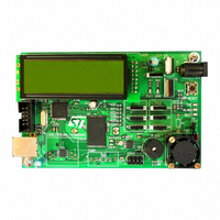
STEVAL-IFS003V1
Description
BOARD STLM75/STDS75/ST72F651
Manufacturer
STMicroelectronics
Datasheets
1.STLM75DS2F.pdf
(40 pages)
2.STDS75M2F.pdf
(39 pages)
3.STEVAL-IFS003V1.pdf
(161 pages)
4.STEVAL-IFS003V1.pdf
(4 pages)
Specifications of STEVAL-IFS003V1
Design Resources
STEVAL-IFS003V1 Gerber Files STEVAL-IFS003V1 Schematic STEVAL-IFS003V1 Bill of Materials
Sensor Type
Temperature
Sensing Range
-55°C ~ 125°C
Interface
I²C
Voltage - Supply
7.5 V ~ 19 V
Embedded
Yes, MCU, 8-Bit
Utilized Ic / Part
ST72F651, STDS75, STLM75
Silicon Manufacturer
ST Micro
Silicon Core Number
STLM75/STDS75 And ST72F651AR6
Kit Application Type
Sensing - Temperature
Application Sub Type
Temperature Sensor
Kit Contents
Board
Lead Free Status / RoHS Status
Lead free / RoHS Compliant
Sensitivity
-
Lead Free Status / Rohs Status
Lead free / RoHS Compliant
Other names
497-6238


ST72651AR6
PWM/BRM GENERATOR (Cont’d)
BRM Generation
The BRM bits allow the addition of a pulse to wid-
en a standard PWM pulse for specific PWM cy-
cles. This has the effect of “fine-tuning” the PWM
Duty cycle (without modifying the base duty cycle),
thus, with the external filtering, providing additional
fine voltage steps.
The incremental pulses (with duration of T
added to the beginning of the original PWM pulse.
The PWM intervals which are added to are speci-
fied in the 4-bit BRM register and are encoded as
shown in the following table. The BRM values
shown may be combined together to provide a
summation of the incremental pulse intervals
specified.
The pulse increment corresponds to the PWM res-
olution.
For example, if
– Data 18h is written to the PWM register
– Data 06h (00000110b) is written to the BRM reg-
– with a 8MHz internal clock (125ns resolution)
Then 3.0 μs-long pulse will be output at 8 μs inter-
vals, except for cycles numbered 2,4,6,10,12,14,
where the pulse is broadened to 3.125 μs.
Figure 51. BRM pulse addition (PWM > 0)
90/161
ister
T
m = 0
CPU
x 64
T
m = 1
CPU
x 64
CPU
Doc ID 7215 Rev 4
T
) are
CPU
T
m = 2
CPU
x 64 increment
x 64
Note. If 00h is written to both PWM and BRM reg-
isters, the generator output will remain at “0”. Con-
versely, if both registers hold data 3Fh and 0Fh,
respectively, the output will remain at “1” for all in-
tervals 1 to 15, but it will return to zero at interval 0
for an amount of time corresponding to the PWM
resolution (T
An output can be set to a continuous “1” level by
clearing the PWM and BRM values and setting
POL = “1” (inverted polarity) in the PWM register.
This allows a PWM/BRM channel to be used as an
additional I/O pin if the DAC function is not re-
quired.
Table 30. Bit BRM Added Pulse Intervals
(Interval #0 not selected).
BRM 4 - Bit Data
0000
0001
0010
0100
1000
CPU
).
none
i = 8
i = 4,12
i = 2,6,10,14
i = 1,3,5,7,9,11,13,15
Incremental Pulse Intervals
T
m = 15
CPU
x 64
Related parts for STEVAL-IFS003V1
Image
Part Number
Description
Manufacturer
Datasheet
Request
R

Part Number:
Description:
BOARD EVAL SPZB260 MOD FOR STR9
Manufacturer:
STMicroelectronics
Datasheet:

Part Number:
Description:
BOARD EVAL EXTENSION SN250
Manufacturer:
STMicroelectronics
Datasheet:

Part Number:
Description:
BOARD EVAL AB-54003L-512
Manufacturer:
STMicroelectronics
Datasheet:

Part Number:
Description:
BOARD REF DESIGN RF DMOS PWR AMP
Manufacturer:
STMicroelectronics
Datasheet:

Part Number:
Description:
BOARD EVAL PWR AMP AB-84008L-470
Manufacturer:
STMicroelectronics
Datasheet:

Part Number:
Description:
BOARD EVAL FOR STM32F103XX
Manufacturer:
STMicroelectronics
Datasheet:

Part Number:
Description:
BOARD EVAL AB-54003L-512
Manufacturer:
STMicroelectronics
Datasheet:

Part Number:
Description:
BOARD SMART PLUG STM32 SPZB260PR
Manufacturer:
STMicroelectronics
Datasheet:

Part Number:
Description:
BOARD DEMO BLUETOOTH SPBT2532C2
Manufacturer:
STMicroelectronics
Datasheet:
Part Number:
Description:
ZIGBEE USB DONGLE EVAL KIT
Manufacturer:
STMicroelectronics
Datasheet:
Part Number:
Description:
STMicroelectronics [RIPPLE-CARRY BINARY COUNTER/DIVIDERS]
Manufacturer:
STMicroelectronics
Datasheet:
Part Number:
Description:
STMicroelectronics [LIQUID-CRYSTAL DISPLAY DRIVERS]
Manufacturer:
STMicroelectronics
Datasheet:

Part Number:
Description:
BOARD EVAL FOR MEMS SENSORS
Manufacturer:
STMicroelectronics
Datasheet: