STEVAL-IFS003V1 STMicroelectronics, STEVAL-IFS003V1 Datasheet - Page 97
STEVAL-IFS003V1
Manufacturer Part Number
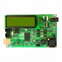
STEVAL-IFS003V1
Description
BOARD STLM75/STDS75/ST72F651
Manufacturer
STMicroelectronics
Datasheets
1.STLM75DS2F.pdf
(40 pages)
2.STDS75M2F.pdf
(39 pages)
3.STEVAL-IFS003V1.pdf
(161 pages)
4.STEVAL-IFS003V1.pdf
(4 pages)
Specifications of STEVAL-IFS003V1
Design Resources
STEVAL-IFS003V1 Gerber Files STEVAL-IFS003V1 Schematic STEVAL-IFS003V1 Bill of Materials
Sensor Type
Temperature
Sensing Range
-55°C ~ 125°C
Interface
I²C
Voltage - Supply
7.5 V ~ 19 V
Embedded
Yes, MCU, 8-Bit
Utilized Ic / Part
ST72F651, STDS75, STLM75
Silicon Manufacturer
ST Micro
Silicon Core Number
STLM75/STDS75 And ST72F651AR6
Kit Application Type
Sensing - Temperature
Application Sub Type
Temperature Sensor
Kit Contents
Board
Lead Free Status / RoHS Status
Lead free / RoHS Compliant
Sensitivity
-
Lead Free Status / Rohs Status
Lead free / RoHS Compliant
Other names
497-6238


SERIAL PERIPHERAL INTERFACE (Cont’d)
11.6.3.3 Master Mode Operation
In master mode, the serial clock is output on the
SCK pin. The clock frequency, polarity and phase
are configured by software (refer to the description
of the SPICSR register).
Note: The idle state of SCK must correspond to
the polarity selected in the SPICSR register (by
pulling up SCK if CPOL=1 or pulling down SCK if
CPOL=0).
To operate the SPI in master mode, perform
the following two steps in order (if the SPICSR
register is not written first, the SPICR register
setting (MSTR bit) may be not taken into ac-
count):
1. Write to the SPICR register:
2. Write to the SPICSR register:
3. Write to the SPICR register:
The transmit sequence begins when software
writes a byte in the SPIDR register.
11.6.3.4 Master Mode Transmit Sequence
When software writes to the SPIDR register, the
data byte is loaded into the 8-bit shift register and
then shifted out serially to the MOSI pin most sig-
nificant bit first.
When data transfer is complete:
Clearing the SPIF bit is performed by the following
software sequence:
1. An access to the SPICSR register while the
2. A read to the SPIDR register.
– Select the clock frequency by configuring the
– Select the clock polarity and clock phase by
– Either set the SSM bit and set the SSI bit or
– Set the MSTR and SPE bits
– The SPIF bit is set by hardware
– An interrupt request is generated if the SPIE
SPIF bit is set
SPR[2:0] bits.
configuring the CPOL and CPHA bits.
59
Note: The slave must have the same CPOL
and CPHA settings as the master.
clear the SSM bit and tie the SS pin high for
the complete byte transmit sequence.
Note: MSTR and SPE bits remain set only if
SS is high).
bit is set and the interrupt mask in the CC reg-
ister is cleared.
shows the four possible configurations.
Figure
Doc ID 7215 Rev 4
Note: While the SPIF bit is set, all writes to the
SPIDR register are inhibited until the SPICSR reg-
ister is read.
11.6.3.5 Slave Mode Operation
In slave mode, the serial clock is received on the
SCK pin from the master device.
To operate the SPI in slave mode:
1. Write to the SPICSR register to perform the fol-
2. Write to the SPICR register to clear the MSTR
11.6.3.6 Slave Mode Transmit Sequence
When software writes to the SPIDR register, the
data byte is loaded into the 8-bit shift register and
then shifted out serially to the MISO pin most sig-
nificant bit first.
The transmit sequence begins when the slave de-
vice receives the clock signal and the most signifi-
cant bit of the data on its MOSI pin.
When data transfer is complete:
Clearing the SPIF bit is performed by the following
software sequence:
1. An access to the SPICSR register while the
2. A write or a read to the SPIDR register.
Notes: While the SPIF bit is set, all writes to the
SPIDR register are inhibited until the SPICSR reg-
ister is read.
The SPIF bit can be cleared during a second
transmission; however, it must be cleared before
the second SPIF bit in order to prevent an Overrun
condition (see
lowing actions:
– Select the clock polarity and clock phase by
– Manage the SS pin as described in
bit and set the SPE bit to enable the SPI I/O
functions.
– The SPIF bit is set by hardware
– An interrupt request is generated if SPIE bit is
SPIF bit is set.
configuring the CPOL and CPHA bits (see
Figure
Note: The slave must have the same CPOL
and CPHA settings as the master.
11.6.3.2
be held low continuously. If CPHA=0 SS must
be held low during byte transmission and
pulled up between each byte to let the slave
write in the shift register.
set and interrupt mask in the CC register is
cleared.
59).
and
Section
Figure
11.6.5.2).
57. If CPHA=1 SS must
ST72651AR6
Section
97/161
Related parts for STEVAL-IFS003V1
Image
Part Number
Description
Manufacturer
Datasheet
Request
R

Part Number:
Description:
BOARD EVAL SPZB260 MOD FOR STR9
Manufacturer:
STMicroelectronics
Datasheet:

Part Number:
Description:
BOARD EVAL EXTENSION SN250
Manufacturer:
STMicroelectronics
Datasheet:

Part Number:
Description:
BOARD EVAL AB-54003L-512
Manufacturer:
STMicroelectronics
Datasheet:

Part Number:
Description:
BOARD REF DESIGN RF DMOS PWR AMP
Manufacturer:
STMicroelectronics
Datasheet:

Part Number:
Description:
BOARD EVAL PWR AMP AB-84008L-470
Manufacturer:
STMicroelectronics
Datasheet:

Part Number:
Description:
BOARD EVAL FOR STM32F103XX
Manufacturer:
STMicroelectronics
Datasheet:

Part Number:
Description:
BOARD EVAL AB-54003L-512
Manufacturer:
STMicroelectronics
Datasheet:

Part Number:
Description:
BOARD SMART PLUG STM32 SPZB260PR
Manufacturer:
STMicroelectronics
Datasheet:

Part Number:
Description:
BOARD DEMO BLUETOOTH SPBT2532C2
Manufacturer:
STMicroelectronics
Datasheet:
Part Number:
Description:
ZIGBEE USB DONGLE EVAL KIT
Manufacturer:
STMicroelectronics
Datasheet:
Part Number:
Description:
STMicroelectronics [RIPPLE-CARRY BINARY COUNTER/DIVIDERS]
Manufacturer:
STMicroelectronics
Datasheet:
Part Number:
Description:
STMicroelectronics [LIQUID-CRYSTAL DISPLAY DRIVERS]
Manufacturer:
STMicroelectronics
Datasheet:

Part Number:
Description:
BOARD EVAL FOR MEMS SENSORS
Manufacturer:
STMicroelectronics
Datasheet: