STEVAL-IFS003V1 STMicroelectronics, STEVAL-IFS003V1 Datasheet - Page 54
STEVAL-IFS003V1
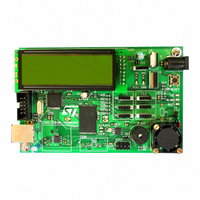
Manufacturer Part Number
STEVAL-IFS003V1
Description
BOARD STLM75/STDS75/ST72F651
Manufacturer
STMicroelectronics
Datasheets
1.STLM75DS2F.pdf
(40 pages)
2.STDS75M2F.pdf
(39 pages)
3.STEVAL-IFS003V1.pdf
(161 pages)
4.STEVAL-IFS003V1.pdf
(4 pages)
Specifications of STEVAL-IFS003V1
Design Resources
STEVAL-IFS003V1 Gerber Files STEVAL-IFS003V1 Schematic STEVAL-IFS003V1 Bill of Materials
Sensor Type
Temperature
Sensing Range
-55°C ~ 125°C
Interface
I²C
Voltage - Supply
7.5 V ~ 19 V
Embedded
Yes, MCU, 8-Bit
Utilized Ic / Part
ST72F651, STDS75, STLM75
Silicon Manufacturer
ST Micro
Silicon Core Number
STLM75/STDS75 And ST72F651AR6
Kit Application Type
Sensing - Temperature
Application Sub Type
Temperature Sensor
Kit Contents
Board
Lead Free Status / RoHS Status
Lead free / RoHS Compliant
Sensitivity
-
Lead Free Status / Rohs Status
Lead free / RoHS Compliant
Other names
497-6238


ST72651AR6
11 ON-CHIP PERIPHERALS
11.1 WATCHDOG TIMER (WDG)
11.1.1 Introduction
The Watchdog timer is used to detect the occur-
rence of a software fault, usually generated by ex-
ternal interference or by unforeseen logical condi-
tions, which causes the application program to
abandon its normal sequence. The Watchdog cir-
cuit generates an MCU reset on expiry of a pro-
grammed time period, unless the program refresh-
es the counter’s contents before the T6 bit be-
comes cleared.
11.1.2 Main Features
■
■
■
■
11.1.3 Functional Description
The counter value stored in the CR register (bits
T[6:0]), is decremented every 65,536 machine cy-
cles, and the length of the timeout period can be
programmed by the user in 64 increments.
Figure 33. Watchdog Block Diagram
54/161
1
Programmable free-running downcounter (64
increments of 65536 CPU cycles)
Programmable reset
Reset (if watchdog activated) when the T6 bit
reaches zero
Hardware Watchdog selectable by option byte
f
CPU
WDGA
RESET
T6
T5
WATCHDOG CONTROL REGISTER (CR)
7-BIT DOWNCOUNTER
CLOCK DIVIDER
T4
Doc ID 7215 Rev 4
÷65536
T3
If the watchdog is activated (the WDGA bit is set)
and when the 7-bit timer (bits T[6:0]) rolls over
from 40h to 3Fh (T6 becomes cleared), it initiates
a reset cycle pulling low the reset pin for typically
500ns.
The application program must write in the CR reg-
ister at regular intervals during normal operation to
prevent an MCU reset. This downcounter is free-
running: it counts down even if the watchdog is
disabled. The value to be stored in the CR register
must be between FFh and C0h (see
– The WDGA bit is set (watchdog enabled)
– The T6 bit is set to prevent generating an imme-
– The T[5:0] bits contain the number of increments
Table 17.Watchdog Timing (f
diate reset
which represents the time delay before the
watchdog produces a reset.
Max
T2
Min
T1
CR Register
initial value
T0
C0h
FFh
WDG timeout period
CPU
= 8 MHz)
524.288
Table
8.192
(ms)
17):
Related parts for STEVAL-IFS003V1
Image
Part Number
Description
Manufacturer
Datasheet
Request
R

Part Number:
Description:
BOARD EVAL SPZB260 MOD FOR STR9
Manufacturer:
STMicroelectronics
Datasheet:

Part Number:
Description:
BOARD EVAL EXTENSION SN250
Manufacturer:
STMicroelectronics
Datasheet:

Part Number:
Description:
BOARD EVAL AB-54003L-512
Manufacturer:
STMicroelectronics
Datasheet:

Part Number:
Description:
BOARD REF DESIGN RF DMOS PWR AMP
Manufacturer:
STMicroelectronics
Datasheet:

Part Number:
Description:
BOARD EVAL PWR AMP AB-84008L-470
Manufacturer:
STMicroelectronics
Datasheet:

Part Number:
Description:
BOARD EVAL FOR STM32F103XX
Manufacturer:
STMicroelectronics
Datasheet:

Part Number:
Description:
BOARD EVAL AB-54003L-512
Manufacturer:
STMicroelectronics
Datasheet:

Part Number:
Description:
BOARD SMART PLUG STM32 SPZB260PR
Manufacturer:
STMicroelectronics
Datasheet:

Part Number:
Description:
BOARD DEMO BLUETOOTH SPBT2532C2
Manufacturer:
STMicroelectronics
Datasheet:
Part Number:
Description:
ZIGBEE USB DONGLE EVAL KIT
Manufacturer:
STMicroelectronics
Datasheet:
Part Number:
Description:
STMicroelectronics [RIPPLE-CARRY BINARY COUNTER/DIVIDERS]
Manufacturer:
STMicroelectronics
Datasheet:
Part Number:
Description:
STMicroelectronics [LIQUID-CRYSTAL DISPLAY DRIVERS]
Manufacturer:
STMicroelectronics
Datasheet:

Part Number:
Description:
BOARD EVAL FOR MEMS SENSORS
Manufacturer:
STMicroelectronics
Datasheet: