OM11027 NXP Semiconductors, OM11027 Datasheet - Page 57
OM11027
Manufacturer Part Number
OM11027
Description
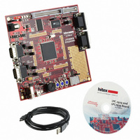
BOARD EVAL LPC2939
Manufacturer
NXP Semiconductors
Type
MCUr
Datasheet
1.OM11027.pdf
(99 pages)
Specifications of OM11027
Contents
Board
For Use With/related Products
LPC2939
Lead Free Status / RoHS Status
Lead free / RoHS Compliant
Other names
568-4787


NXP Semiconductors
LPC2939_3
Product data sheet
Fig 15. Block diagram of the CGU1
BASE_ICLK0_CLK
BASE_ICLK1_CLK
6.16.3.1 Pin description
6.16.3 Clock generation for USB (CGU1)
6.16.4 Reset Generation Unit (RGU)
The CGU1 block is functionally identical to the CGU0 block and generates two clocks for
the USB interface and a dedicated output clock. The CGU1 block uses its own PLL and
fractional divider. The PLLs used in CGU0 and CGU1 are identical (see
The clock input to the CGU1 PLL is provided by one of two base clocks generated in the
CGU0: BASE_ICLK0_CLK or BASE_ICLK1_CLK. The base clock not used for the PLL
can be configured to drive the output clock directly.
The CGU1 module in the LPC2939 has the pins listed in
Table 29.
The RGU controls all internal resets.
The key features of the Reset Generation Unit (RGU) are:
Symbol
CLK_OUT
•
•
PLL
CLOCK GENERATION UNIT
Reset controlled individually per subsystem
Automatic reset stretching and release
clkout
clkout120
clkout240
(CGU1)
CGU1 pins
All information provided in this document is subject to legal disclaimers.
Direction
OUT
AHB TO DTL BRIDGE
Rev. 03 — 7 April 2010
FDIV0
Description
clock output
ARM9 microcontroller with CAN, LIN, and USB
Table 28
OUT 0
OUT 1
OUT 2
below.
LPC2939
© NXP B.V. 2010. All rights reserved.
Section
BASE_USB_CLK
BASE_USB_I2C_CLK
BASE_OUT_CLK
002aae148
6.16.2.2).
57 of 99
Related parts for OM11027
Image
Part Number
Description
Manufacturer
Datasheet
Request
R

Part Number:
Description:
NXP Semiconductors designed the LPC2420/2460 microcontroller around a 16-bit/32-bitARM7TDMI-S CPU core with real-time debug interfaces that include both JTAG andembedded trace
Manufacturer:
NXP Semiconductors
Datasheet:

Part Number:
Description:
NXP Semiconductors designed the LPC2458 microcontroller around a 16-bit/32-bitARM7TDMI-S CPU core with real-time debug interfaces that include both JTAG andembedded trace
Manufacturer:
NXP Semiconductors
Datasheet:
Part Number:
Description:
NXP Semiconductors designed the LPC2468 microcontroller around a 16-bit/32-bitARM7TDMI-S CPU core with real-time debug interfaces that include both JTAG andembedded trace
Manufacturer:
NXP Semiconductors
Datasheet:
Part Number:
Description:
NXP Semiconductors designed the LPC2470 microcontroller, powered by theARM7TDMI-S core, to be a highly integrated microcontroller for a wide range ofapplications that require advanced communications and high quality graphic displays
Manufacturer:
NXP Semiconductors
Datasheet:
Part Number:
Description:
NXP Semiconductors designed the LPC2478 microcontroller, powered by theARM7TDMI-S core, to be a highly integrated microcontroller for a wide range ofapplications that require advanced communications and high quality graphic displays
Manufacturer:
NXP Semiconductors
Datasheet:
Part Number:
Description:
The Philips Semiconductors XA (eXtended Architecture) family of 16-bit single-chip microcontrollers is powerful enough to easily handle the requirements of high performance embedded applications, yet inexpensive enough to compete in the market for hi
Manufacturer:
NXP Semiconductors
Datasheet:
Part Number:
Description:
The XA-S3 device is a member of Philips Semiconductors? XA(eXtended Architecture) family of high performance 16-bitsingle-chip microcontrollers
Manufacturer:
NXP Semiconductors
Datasheet:

Part Number:
Description:
The NXP BlueStreak LH75401/LH75411 family consists of two low-cost 16/32-bit System-on-Chip (SoC) devices
Manufacturer:
NXP Semiconductors
Datasheet:
Part Number:
Description:
The NXP LPC3130/3131 combine an 180 MHz ARM926EJ-S CPU core, high-speed USB2
Manufacturer:
NXP Semiconductors
Datasheet:
Part Number:
Description:
The NXP LPC3141 combine a 270 MHz ARM926EJ-S CPU core, High-speed USB 2
Manufacturer:
NXP Semiconductors
Part Number:
Description:
The NXP LPC3143 combine a 270 MHz ARM926EJ-S CPU core, High-speed USB 2
Manufacturer:
NXP Semiconductors

Part Number:
Description:
The NXP LPC3152 combines an 180 MHz ARM926EJ-S CPU core, High-speed USB 2
Manufacturer:
NXP Semiconductors
Part Number:
Description:
The NXP LPC3154 combines an 180 MHz ARM926EJ-S CPU core, High-speed USB 2
Manufacturer:
NXP Semiconductors

Part Number:
Description:
Standard level N-channel enhancement mode Field-Effect Transistor (FET) in a plastic package using NXP High-Performance Automotive (HPA) TrenchMOS technology
Manufacturer:
NXP Semiconductors
Datasheet: