OM11027 NXP Semiconductors, OM11027 Datasheet - Page 88
OM11027
Manufacturer Part Number
OM11027
Description
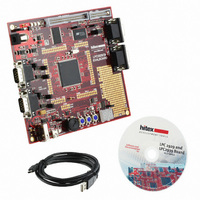
BOARD EVAL LPC2939
Manufacturer
NXP Semiconductors
Type
MCUr
Datasheet
1.OM11027.pdf
(99 pages)
Specifications of OM11027
Contents
Board
For Use With/related Products
LPC2939
Lead Free Status / RoHS Status
Lead free / RoHS Compliant
Other names
568-4787


NXP Semiconductors
LPC2939_3
Product data sheet
10.4 XIN_OSC input
10.5 XIN_OSC Printed-Circuit Board (PCB) layout guidelines
The input voltage to the on-chip oscillators is limited to 1.8 V. If the oscillator is driven by a
clock in slave mode, it is recommended that the input be coupled through a capacitor with
C
capacitor to ground C
slave mode, a minimum of 200 mV RMS is needed. For more details see the LPC29xx
User manual UM10316.
The crystal should be connected on the PCB as close as possible to the oscillator input
and output pins of the chip. Take care that the load capacitors C
case of third overtone crystal usage, have a common ground plane. The external
components must also be connected to the ground plain. Loops must be made as small
as possible, in order to keep the noise coupled in via the PCB as small as possible. Also
parasitics should stay as small as possible. Values of C
smaller accordingly to the increase in parasitics of the PCB layout.
Fig 39. Slave mode operation of the on-chip oscillator
i
= 100 pF. To limit the input voltage to the specified range, choose an additional
All information provided in this document is subject to legal disclaimers.
g
which attenuates the input voltage by a factor C
Rev. 03 — 7 April 2010
XIN_OSC
C i
100 pF
ARM9 microcontroller with CAN, LIN, and USB
LPC29xx
002aae730
C g
x1
and C
x2
x1
should be chosen
and C
LPC2939
i
© NXP B.V. 2010. All rights reserved.
/ (C
x2
, and C
i
+ C
g
). In
x3
88 of 99
in
Related parts for OM11027
Image
Part Number
Description
Manufacturer
Datasheet
Request
R

Part Number:
Description:
NXP Semiconductors designed the LPC2420/2460 microcontroller around a 16-bit/32-bitARM7TDMI-S CPU core with real-time debug interfaces that include both JTAG andembedded trace
Manufacturer:
NXP Semiconductors
Datasheet:

Part Number:
Description:
NXP Semiconductors designed the LPC2458 microcontroller around a 16-bit/32-bitARM7TDMI-S CPU core with real-time debug interfaces that include both JTAG andembedded trace
Manufacturer:
NXP Semiconductors
Datasheet:
Part Number:
Description:
NXP Semiconductors designed the LPC2468 microcontroller around a 16-bit/32-bitARM7TDMI-S CPU core with real-time debug interfaces that include both JTAG andembedded trace
Manufacturer:
NXP Semiconductors
Datasheet:
Part Number:
Description:
NXP Semiconductors designed the LPC2470 microcontroller, powered by theARM7TDMI-S core, to be a highly integrated microcontroller for a wide range ofapplications that require advanced communications and high quality graphic displays
Manufacturer:
NXP Semiconductors
Datasheet:
Part Number:
Description:
NXP Semiconductors designed the LPC2478 microcontroller, powered by theARM7TDMI-S core, to be a highly integrated microcontroller for a wide range ofapplications that require advanced communications and high quality graphic displays
Manufacturer:
NXP Semiconductors
Datasheet:
Part Number:
Description:
The Philips Semiconductors XA (eXtended Architecture) family of 16-bit single-chip microcontrollers is powerful enough to easily handle the requirements of high performance embedded applications, yet inexpensive enough to compete in the market for hi
Manufacturer:
NXP Semiconductors
Datasheet:
Part Number:
Description:
The XA-S3 device is a member of Philips Semiconductors? XA(eXtended Architecture) family of high performance 16-bitsingle-chip microcontrollers
Manufacturer:
NXP Semiconductors
Datasheet:

Part Number:
Description:
The NXP BlueStreak LH75401/LH75411 family consists of two low-cost 16/32-bit System-on-Chip (SoC) devices
Manufacturer:
NXP Semiconductors
Datasheet:
Part Number:
Description:
The NXP LPC3130/3131 combine an 180 MHz ARM926EJ-S CPU core, high-speed USB2
Manufacturer:
NXP Semiconductors
Datasheet:
Part Number:
Description:
The NXP LPC3141 combine a 270 MHz ARM926EJ-S CPU core, High-speed USB 2
Manufacturer:
NXP Semiconductors
Part Number:
Description:
The NXP LPC3143 combine a 270 MHz ARM926EJ-S CPU core, High-speed USB 2
Manufacturer:
NXP Semiconductors

Part Number:
Description:
The NXP LPC3152 combines an 180 MHz ARM926EJ-S CPU core, High-speed USB 2
Manufacturer:
NXP Semiconductors
Part Number:
Description:
The NXP LPC3154 combines an 180 MHz ARM926EJ-S CPU core, High-speed USB 2
Manufacturer:
NXP Semiconductors

Part Number:
Description:
Standard level N-channel enhancement mode Field-Effect Transistor (FET) in a plastic package using NXP High-Performance Automotive (HPA) TrenchMOS technology
Manufacturer:
NXP Semiconductors
Datasheet: