101-0401 Rabbit Semiconductor, 101-0401 Datasheet
101-0401
Specifications of 101-0401
316-1005
Q906133


Related parts for 101-0401


101-0401 Summary of contents
Page 1
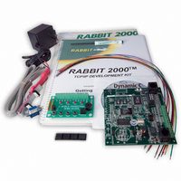
TCP/IP Development Kit Integrated C Development System Getting Started Manual 019–0079 • 040531–G ...
Page 2
... Rabbit Semiconductor • All rights reserved. Rabbit Semiconductor reserves the right to make changes and improvements to its products without providing notice. Trademarks Rabbit 2000 is a registered trademark of Rabbit Semiconductor. Dynamic registered trademark of Z-World Inc. Rabbit Semiconductor 2932 Spafford Street Davis, California 95616-6800 ...
Page 3
Chapter 1. Overview 1.1 Description...........................................................................................................................................1 1.1.1 TCP/IP Development Board Features...........................................................................................1 1.1.2 Key Benefits..................................................................................................................................2 1.1.3 TCP/IP Capabilities.......................................................................................................................2 1.2 Physical and Electrical Specifications ..................................................................................................3 1.3 Development Software .........................................................................................................................4 1.4 How to Use This Manual ......................................................................................................................5 1.4.1 Additional Reference Information ................................................................................................5 1.4.2 Using ...
Page 4
Chapter 4. Using the TCP/IP Features 4.1 TCP/IP Connections ........................................................................................................................... 29 4.2 Primer on IP Addresses ...................................................................................................................... 32 4.3 IP Addresses Explained...................................................................................................................... 33 4.4 How IP Addresses are Used ............................................................................................................... 34 4.5 Dynamically Assigned Internet Addresses ........................................................................................ 35 4.6 Placing ...
Page 5
The TCP/IP Development Kit provides a hardware platform based on the Rabbit 2000 the tools necessary to develop a robust 10Base-T Ethernet appli- cation. 1.1 Description The TCP/IP Development Kit includes a TCP/IP Development Board (with a Rabbit ® 2000 ...
Page 6
Key Benefits • Ethernet ready—port to an Ethernet chip is done for the Rabbit 2000 chip. • Cost-effective—no run-time royalties. • Simplified development—a complete Dynamic C software package (with integrated editor, compiler and debugger) is provided. No in-circuit emulator ...
Page 7
Physical and Electrical Specifications Table 1 lists the basic specifications for the TCP/IP Development Board. Table 1. TCP/IP Development Board Specifications Specification Power Supply Board Size (with optional backup-battery board) Environmental The TCP/IP Development Board has 15 pins on ...
Page 8
Development Software The TCP/IP Development Board uses the Dynamic C development environment for rapid creation and debugging of runtime applications. Dynamic C provides a complete develop- ment environment with integrated editor, compiler and source-level debugger. It interfaces directly with ...
Page 9
How to Use This Manual This Getting Started manual is intended to give users a quick but solid start with the TCP/IP Development Board. It does not contain detailed information on the hardware capabilities or the Dynamic C development ...
Page 10
Printing Electronic Manuals We recognize that many users prefer printed manuals for some uses. Users can easily print all or parts of those manuals provided in electronic form. The following guidelines may be helpful: • Print from the Adobe PDF ...
Page 11
CE Compliance Equipment is generally divided into two classes. CLASS A Digital equipment meant for light industrial use Less restrictive emissions requirement: less than 40 dB µV (40 dB relative to 1 µV/m) or 300 µV/m ...
Page 12
... When connecting the TCP/IP Development Board to outdoor cables, the customer is responsible for providing CE-approved surge/lighting protection. • Rabbit Semiconductor recommends placing digital I/O or analog cables that are longer in a metal conduit to assist in maintaining CE compliance and to conform to good cable design practices. ...
Page 13
H Chapter 2 explains how to connect the power supply to the TCP/IP Development Board and how to connect the program- ming cable to your PC. Once you run a sample program to dem- onstrate that you have connected ...
Page 14
Connections 1. Attach the rubber feet to the bottom corners of the TCP/IP Development Board. 2. Connect the Programming Cable to the TCP/IP Development Board Turn the Rabbit 2000 TCP/IP Development Board so that the Rabbit 2000 microprocessor is ...
Page 15
Connect Power Supply to TCP/IP Development Board Connect the positive lead (indicated with red heat-shrink tubing) to the PWR connector on header J7 on the TCP/IP Development Board and connect the negative lead to GND on header J7 as ...
Page 16
... Technical Support NOTE: If you purchased your TCP/IP Development Board through a distributor or through a Z-World or Rabbit Semiconductor partner, contact the distributor or Z-World partner first for technical support. If there are any problems at this point: • Check the Z-World/Rabbit Semiconductor Technical Bulletin Board at www.zworld.com/support/bb/. • ...
Page 17
... To develop and debug programs for the TCP/IP Development Board (and for all other Z-World and Rabbit Semiconductor hardware), you must install and use Dynamic C. This chapter takes you through the installation of Dynamic C, and then pro- vides a tour of its major features with respect to the TCP/IP Development Board ...
Page 18
Dynamic C provides extensions to the C language (such as shared and protected vari- ables, costatements and cofunctions) that support real-world embedded system devel- opment. Interrupt service routines may be written in C. Dynamic C supports cooperative and preemptive ...
Page 19
Upgrading Dynamic C Dynamic C patches that focus on bug fixes are available from time to time. Check the Web sites • www.zworld.com/support/ or • www.rabbitsemiconductor.com/support/ for the latest patches, workarounds, and bug fixes. 3.3.1 Add-On Modules Dynamic C ...
Page 20
Installing Dynamic C Insert the Dynamic C CD-ROM in the drive on your PC. If autorun is enabled, the CD installation will begin automatically. If autorun is disabled or the installation otherwise does not start, use the Windows menu ...
Page 21
Installation Type Dynamic C has two components that can be installed together or separately. One compo- nent is Dynamic C itself, with the development environment, support files and libraries. The other component is the documentation library in HTML and ...
Page 22
Select COM Port Dynamic C uses a COM (serial) port to communicate with the target development system. The installation allows you to choose the COM port that will be used. The default selection, as shown in the example above, ...
Page 23
Starting Dynamic C Once the TCP/IP Development Board is set up and connected as described in Chapter 2 and Dynamic C has been installed, start Dynamic C by double-clicking on the Dynamic C icon. Dynamic C defaults to using ...
Page 24
PONG.C You are now ready to test your set-up by running a sample program. Find the file , which is in the Dynamic C PONG.C open it with the menu ( not still open), compile it using ...
Page 25
Sample Programs Sample programs are provided in the Dynamic C rectories contain specific sample programs that illustrate the use of the corresponding Dynamic C libraries. The sample program window. The and ICOM TCPIP Development Board. The sample programs illustrate ...
Page 26
Now, open the file DEMOBRD1.C will appear in a window, as shown in Figure 5 below (minus some comments). Use the mouse to place the cursor on the function name . This will bring up a documentation box for the ...
Page 27
The programming cable must be connected to the TCP/IP Development Board. (The colored wire on the programming cable is closest to pin 1 on header J4 on the TCP/IP Development Board, as shown in Figure 1.) The other end ...
Page 28
Editing the Program Click on the box on the task bar. This will set Dynamic C into the edit mode so that Edit you can change the program. Use the with a new name so as not to change ...
Page 29
This will cause the program to break if the execution thread hits your break point. • Watch expressions. A watch expression expression that is evaluated on command in the watch window. ...
Page 30
WrPortI(PDDDR, &PDDDRShadow, 0x03); // set port D bits 0-1 as outputs WrPortI(PDDCR, &PDDCRShadow, 0x00); // set port D to not open drain mode vswitch = 0; (1) while ( First task will flash LED4 ...
Page 31
If a tered, then a jump is made to the end of the costatement (4), and on the next pass of the loop, when ...
Page 32
Spectrum Spreader TCP/IP Development Boards that carry the CE mark have a Rabbit 2000 microprocessor that features a spectrum spreader, which helps to mitigate EMI problems. By default, the spectrum spreader is on automatically for TCP/IP Development Boards that ...
Page 33
... Two RJ-45 straight through Ethernet cables and a hub RJ-45 crossover Ethernet cable. The Ethernet cables and Ethernet hub are available from Rabbit Semiconductor in a TCP/IP tool kit. More information is available at www.rabbitsemiconductor.com. 1. Connect the AC adapter and the programming cable as shown in Section 2.2, “Connec- tions.” ...
Page 34
The following options require more care in address selection and testing actions, as conflicts with other users, servers and systems can occur: Connect the TCP/IP Development Board’s Ethernet port to an existing LAN, LAN — • preferably one to which ...
Page 35
Getting Started Figure 6. Ethernet Connections 31 ...
Page 36
Primer on IP Addresses Obtaining IP addresses to interact over an existing, operating, network can involve a num- ber of complications, and must usually be done with cooperation from your ISP and/or network systems administrator. For this reason, we ...
Page 37
IP Addresses Explained IP (Internet Protocol) addresses are expressed as 4 decimal numbers separated by periods, for example: 216.103.126.155 10.1.1.6 Each decimal number must be between 0 and 255. The total IP address is a 32-bit number consisting of ...
Page 38
How IP Addresses are Used The actual hardware connection via an Ethernet uses Ethernet adapter addresses (also called MAC addresses). These are 48-bit addresses and are unique for every Ethernet adapter manufactured. In order to send a packet to ...
Page 39
Dynamically Assigned Internet Addresses In many instances, devices on a network do not have fixed IP addresses. This is the case when, for example, you are assigned an IP address dynamically by your Internet service provider (ISP) or when ...
Page 40
Placing Your Device on the Network In many corporate settings, users are isolated from the Internet by a firewall and/or a proxy server. These devices attempt to secure the company from unauthorized network traffic, and usually work by disallowing ...
Page 41
Running TCP/IP Sample Programs We have provided a number of sample programs demonstrating various uses of TCP/IP for networking embedded systems. These programs require you to connect your PC and the TCP/IP Development Board board together on the same ...
Page 42
How to Set IP Addresses in the Sample Programs With the introduction of Dynamic C 7.30 we have taken steps to make it easier to run many of our sample programs. You will see a Dynamic C to select ...
Page 43
... IP address automatically.”) You may want to write down the existing values in case you have to restore them later not necessary to edit the gate- way address since the gateway is not used with direct connect. IP 10.10.6.101 Netmask 255.255.255.0 Direct Connection PC to TCP/IP Development Board Getting Started , do the following ...
Page 44
Run the PINGME.C Demo Connect the crossover cable from your computer’s Ethernet port to the TCP/IP Develop- ment Board’s RJ-45 Ethernet connector. Open the folder, compile the program, and start it running under Dynamic SAMPLES\TCPIP\ICMP C. When the program ...
Page 45
... STDIO 4.10 Where From Here? NOTE: If you purchased your TCP/IP Development Board through a distributor or through a Z-World or Rabbit Semiconductor partner, contact the distributor or Z-World partner first for technical support. If there are any problems at this point: • Check the Z-World/Rabbit Semiconductor Technical Bulletin Board at www.zworld.com/support/bb/. • ...
Page 46
TCP/IP Development Kit ...
Page 47
S ERIAL Chapter 5 describes how to set up TCP/IP Development boards for serial communication, and how to use the digital I/O. Getting Started P D ORTS AND I/O IGITAL 43 ...
Page 48
Serial Communication In the factory-default configuration, the TCP/IP Development Board has one RS-232 (3-wire) serial channel, one RS-485 serial channel, and one synchronous CMOS serial channel. The TCP/IP Development Board may be configured for 5-wire RS-232 or two 3-wire ...
Page 49
Version 175-0188 Rev. C The RS-232 transceiver may be used as a 5-wire RS-232 channel or as two 3-wire RS-232 channels at the expense of the RS-485 channel, which is connected through 0 mounted resistors at R82 and R83 as ...
Page 50
Version 175-0206 The RS-232 transceiver may be used as a 5-wire RS-232 channel or as two 3-wire RS-232 channels at the expense of the RS-485 channel, which is connected through jumpers across header JP7 as shown in Figure 7(c). The ...
Page 51
RS-232 The TCP/IP Development Board’s RS-232 serial channel is connected to an RS-232 trans- ceiver, U11. U11 provides the voltage output, slew rate, and input voltage immunity required to meet the RS-232 serial communication protocol. Basically, the chip translates ...
Page 52
The TCP/IP Development Board comes with a 220 bias resistors installed and enabled with jumpers across pins 1–2 and 5–6 on header JP6, as shown in Figure Figure 8. RS-485 Termination and Bias Resistors The bias ...
Page 53
Serial Communication Software Library files included with Dynamic C provide a full range of serial communications sup- port. The library provides a set of circular-buffer-based serial functions. The RS232.LIB library provides packet-based serial functions where packets can be delim- ...
Page 54
Connect shown in Figure 9 below. Figure 9. TCP/IP Development Board Setup for RS-232 Serial Communication Demonstration 2. Connect the programming cable to header J4 on the TCP/IP Development Board. Apply power to the TCP/IP ...
Page 55
RS-485 1. Connect 485+ to 485+, 485– to 485–, and GND to GND as shown in Figure 10 below. If you do not have a separate wall transformer for the other board, also connect PWR to PWR as shown in ...
Page 56
Digital I/O 5.2.1 Digital Inputs Pins 8–11 on header J7 have the four digital inputs IN0–IN3. Each of the four digital inputs is protected over a range of – +36 V. The ...
Page 57
Digital I/O Software void digOut (int channel, int value); Sets the state of a digital output. PARAMETERS is the output channel number ( 3). channel is the output value (0 or 1). value RETURN VALUE None. ...
Page 58
TCP/IP Development Kit ...
Page 59
D EVELOPMENT Getting Started A A. TCP/IP PPENDIX B S OARD PECIFICATIONS 55 ...
Page 60
A.1 Electrical and Mechanical Specifications Figure A-1 shows the mechanical dimensions for the TCP/IP Development Board. Figure A-1. TCP/IP Development Board Dimensions 56 TCP/IP Development Kit ...
Page 61
Table A-1 lists the electrical, mechanical, and environmental specifications for the TCP/IP Development Board. Table A-1. TCP/IP Development Board Specifications Feature Microprocessor Ethernet Port Flash EPROM SRAM Backup Battery Keypad/Display Digital Inputs Digital Outputs Speaker Output Serial Ports Serial Rate ...
Page 62
A.2 Jumper Configurations Figure A-2 shows the header locations used to configure the various TCP/IP Development Board options via jumpers. Figure A-2. Location of TCP/IP Development Board Configurable Positions 58 TCP/IP Development Kit ...
Page 63
Table A-2 lists the configuration options. Table A-2. TCP/IP Development Board Jumper Configurations Header Description JP1 SRAM Size JP2 Flash 1 Memory Size (U5) JP3 Flash 2 Memory Size (U6) Digital Input Pull-Up/Pull-Down JP4 Resistors JP5 Flash Memory Bank Select ...
Page 64
A.3 Conformal Coating The areas around the crystal oscillator and the battery-backup circuit on the TCP/IP Development Board have had the Dow Corning silicone-based 1-2620 conformal coating applied. The conformally coated areas are shown in Figure A-3. The conformal coating ...
Page 65
A PPENDIX Appendix B describes the power circuitry distributed on the TCP/IP Development Board. B.1 Power Supplies Power is supplied to the TCP/IP Development Board from an external source either through header J7 or from another TCP/IP Development Board through ...
Page 66
B.2 Batteries and External Battery Connections A battery board with a 1000 mA·h lithium coin cell is available to provide power to the real-time clock and SRAM when external power is removed from the circuit. This allows the TCP/IP Development ...
Page 67
B.2.1 Battery-Backup Circuit Figure B-3 shows the battery-backup circuitry on the TCP/IP Development Board. Figure B-3. TCP/IP Development Board Battery Backup Circuit The battery-backup circuit serves three purposes: • It reduces the battery voltage to the SRAM and to the ...
Page 68
B.2.2 Power to VRAM Switch The VRAM switch, shown in Figure B-4, allows the battery backup to provide power when the external power goes off. The switch provides an isolation between Vcc and the battery when Vcc goes low. This ...
Page 69
... B.2.4 Installing/Replacing the Backup-Battery Board An optional pluggable backup-battery board is available from Rabbit Semiconductor. To install the backup-battery board, align the battery board over the outline as shown in Figure B-5, and plug it in. Be careful to align the connectors and the backup battery board. Fasten the backup board using a 4-40 × 3/16 screw and lockwasher. ...
Page 70
B.3 Chip Select Circuit Figure B-6 shows a schematic of the chip select circuit. The current drain on the battery in a battery-backed circuit must be kept at a minimum. When the TCP/IP Development Board is not powered, the battery ...
Page 71
Transistors Q5 and Q6 are of opposite polarity so that a rail-to-rail voltage can be passed. When the /CS1 voltage is low, Q5 will conduct. When the /CS1 voltage is high, Q6 will conduct. It takes time for the transistors ...
Page 72
TCP/IP Development Kit ...
Page 73
A PPENDIX Appendix C provides additional information for the Rabbit 2000 ® microprocessor when using the tors on the programming cable. The only when the programming cable is attached to the program- ming connector (header J4) while a new application ...
Page 74
The programming port, which is shown in Figure C-1, can serve as a convenient commu- nications port for field setup or other occasional communication need (for example diagnostic port). If the port is simply to perform a setup ...
Page 75
Once you establish that the programming port will never again be needed for program- ming possible to use the programming port for additional I/O lines. Table C-1 lists the pins available for this alternate configuration. Table C-1. TCP/IP ...
Page 76
TCP/IP Development Kit ...
Page 77
... Specifications are based on characterization of tested sample units rather than testing over temperature and voltage of each unit. Rabbit Semiconductor products may qualify compo- nents to operate within a range of parameters that is different from the manufacturer’s rec- ommended range ...
Page 78
TCP/IP Development Kit ...
Page 79
A assembly language ................ 13 assembly window .................. 13 B backup battery board ............. 65 installing ............................ 65 battery backup circuit ........... 63 battery connections ............... 62 battery life ............................. language ...................... 13 compliance design ...
Page 80
R real-time kernel (RTK) .....................14 programming .....................14 registers window ..............................13 reset .................................11, 48 reset generator ...................64 RS-232 ..................................47 RS-485 ..................................47 termination and bias resis- tors .................................48 RTK (real-time ...
Page 81
TCP/IP Development Board Schematic www.rabbitsemiconductor.com/documentation/schemat/090-0095.pdf 090-0042 Demonstration Board Schematic www.rabbitsemiconductor.com/documentation/schemat/090-0042.pdf 090-0128 Programming Cable Schematic www.rabbitsemiconductor.com/documentation/schemat/090-0128.pdf The schematics included with the printed manual were the latest revisions available at the time the manual was last revised. The online versions of ...
Page 82
...