101-0401 Rabbit Semiconductor, 101-0401 Datasheet - Page 51
101-0401
Manufacturer Part Number
101-0401
Description
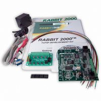
KIT DEV RABBIT2000/TCP/IP
Manufacturer
Rabbit Semiconductor
Series
RabbitCore 2000r
Type
MPU Moduler
Datasheet
1.101-0402.pdf
(82 pages)
Specifications of 101-0401
Rohs Status
RoHS non-compliant
Contents
Rabbit 2000™ TCP/IP Development Board, Demo Board, Power Supply, Cable and Software
Processor To Be Evaluated
Rabbit 2000
Interface Type
RS-232, RS-485
For Use With/related Products
RCM2000, RCM2010, RCM2020
Lead Free Status / Rohs Status
Lead free / RoHS Compliant
Other names
101-0401
316-1005
Q906133
316-1005
Q906133


5.1.1 RS-232
The TCP/IP Development Board’s RS-232 serial channel is connected to an RS-232 trans-
ceiver, U11. U11 provides the voltage output, slew rate, and input voltage immunity
required to meet the RS-232 serial communication protocol. Basically, the chip translates
the Rabbit 2000’s 0 V to +Vcc signals to RS-232 signal levels. Note that the polarity is
reversed in an RS-232 circuit so that +5 V is output as approximately -10 V and 0 V is out-
put as approximately +10 V. U11 also provides the proper line loading for reliable commu-
nication.
The maximum baud rate is 115,200 bps. RS-232 can be used effectively at this baud rate
for distances up to 15 m.
5.1.2 RS-485
The TCP/IP Development Board has one RS-485 serial channel, which is connected to the
Rabbit 2000 Serial Port B through U10, an RS-485 transceiver. The chip’s slew rate limit-
ers provide for a maximum baud rate of 250,000 bps, which allows for a network of up to
1200 m (or 4000 ft). The half-duplex communication uses the Rabbit 2000’s PC0 pin to
control the data enable on the communication line.
The RS-485 signals are available on pins 3 and 4 of header J7, and on J5, the RJ-12 jack.
The TCP/IP Development Board can be used in an RS-485 multidrop network. Connect
the 485+ to 485+ and 485– to 485– using single twisted-pair wires (nonstranded, tinned).
Alternatively, the RS-485 multidrop network may be hooked up using cables with RJ-12 plugs.
Note that the RJ-12 jack has +RAW_485 and GND, which means that only one TCP/IP Devel-
opment Board needs to be connected to an external power source via an AC adapter. When
doing so, ensure that the AC adapter has sufficient capacity for the network — each TCP/IP
Development Board nominally draws 100 mA at 24 VDC.
Getting Started
NOTE: The RS-485 port is available only in the factory default configuration. The RS-485
CAUTION: If you plan to connect a power supply to more than one TCP/IP Devel-
opment Board in an RS-485 network using the RJ-12 jacks, rework the RS-485 cables
so they do not connect +RAW_RS485 through the RJ-12 jack to the boards in the
network.
port will not be available when you select the configuration option for both 3-wire
RS-232 ports or one 5-wire RS-232 port.
47
Related parts for 101-0401
Image
Part Number
Description
Manufacturer
Datasheet
Request
R

Part Number:
Description:
COMPUTER SNGLBD BL2101 A/D 0-10V
Manufacturer:
Rabbit Semiconductor
Part Number:
Description:
CARD D/A 0-10V SR9400 SMARTSTAR
Manufacturer:
Rabbit Semiconductor
Datasheet:
Part Number:
Description:
CARD A/D 0-10V SR9300 SMARTSTAR
Manufacturer:
Rabbit Semiconductor
Datasheet:

Part Number:
Description:
WiFi / 802.11 Modules & Development Tools WIRELESS CONTROL APP KIT
Manufacturer:
Rabbit Semiconductor
Part Number:
Description:
KIT TOOL FOR OP7100
Manufacturer:
Rabbit Semiconductor
Datasheet:

Part Number:
Description:
KIT DEV RABBIT2000/RCM2000
Manufacturer:
Rabbit Semiconductor
Datasheet:
Part Number:
Description:
MODULE RABBITCORE RCM3720
Manufacturer:
Rabbit Semiconductor
Datasheet:
Part Number:
Description:
MODULE RABBITCORE RCM3220
Manufacturer:
Rabbit Semiconductor
Datasheet:
Part Number:
Description:
MODULE RABBITCORE RCM3210
Manufacturer:
Rabbit Semiconductor
Datasheet:
Part Number:
Description:
COMPUTER SGL-BOARD OP6600 W/SRAM
Manufacturer:
Rabbit Semiconductor
Datasheet:
Part Number:
Description:
COMPUTER SGL-BD BL2000 SRAM/FLSH
Manufacturer:
Rabbit Semiconductor