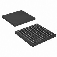
AT91SAM9R64-CU Atmel, AT91SAM9R64-CU Datasheet - Page 710

AT91SAM9R64-CU
Manufacturer Part Number
AT91SAM9R64-CU
Description
MCU ARM9 64K SRAM 144-LFBGA
Manufacturer
Atmel
Series
AT91SAMr
Specifications of AT91SAM9R64-CU
Core Processor
ARM9
Core Size
16/32-Bit
Speed
240MHz
Connectivity
EBI/EMI, I²C, MMC, SPI, SSC, UART/USART, USB
Peripherals
AC'97, POR, PWM, WDT
Number Of I /o
49
Program Memory Size
32KB (32K x 8)
Program Memory Type
ROM
Ram Size
72K x 8
Voltage - Supply (vcc/vdd)
1.08 V ~ 1.32 V
Data Converters
A/D 3x10b
Oscillator Type
Internal
Operating Temperature
-40°C ~ 85°C
Package / Case
144-LFBGA
Processor Series
AT91SAMx
Core
ARM926EJ-S
Data Bus Width
32 bit
Data Ram Size
64 KB
Interface Type
2-Wire, SPI, SSC, USART
Maximum Clock Frequency
240 MHz
Number Of Programmable I/os
118
Number Of Timers
4
Maximum Operating Temperature
+ 85 C
Mounting Style
SMD/SMT
3rd Party Development Tools
JTRACE-ARM-2M, MDK-ARM, RL-ARM, ULINK2
Development Tools By Supplier
AT91SAM-ICE, AT91-ISP, AT91SAM9RL-EK
Minimum Operating Temperature
- 40 C
On-chip Adc
10 bit, 3 Channel
Controller Family/series
AT91SAM9xxx
No. Of I/o's
49
Ram Memory Size
64KB
Cpu Speed
240MHz
No. Of Timers
3
Rohs Compliant
Yes
Package
144LFBGA
Device Core
ARM926EJ-S
Family Name
91S
Maximum Speed
240 MHz
Operating Supply Voltage
1.8|3.3 V
For Use With
AT91SAM-ICE - EMULATOR FOR AT91 ARM7/ARM9
Lead Free Status / RoHS Status
Lead free / RoHS Compliant
Eeprom Size
-
Lead Free Status / Rohs Status
Lead free / RoHS Compliant
Available stocks
Company
Part Number
Manufacturer
Quantity
Price
Part Number:
AT91SAM9R64-CU
Manufacturer:
ATMEL/爱特梅尔
Quantity:
20 000
- Current page: 710 of 903
- Download datasheet (13Mb)
40.6.1.1
710
Tag Slot
Codec Slot 1
Codec Slot 2
Data Slots [3:12]
AT91SAM9R64/RL64 Preliminary
Slot Description
Table 40-3.
The tag slot, or slot 0, is a 16-bit wide slot that always goes at the beginning of an outgoing or
incoming frame. Within tag slot, the first bit is a global bit that flags the entire frame validity. The
next 12 bit positions sampled by the AC’97 Controller indicate which of the corresponding 12
time slots contain valid data. The slot’s last two bits (combined) called Codec ID, are used to dis-
tinguish primary and secondary codec.
The 16-bit wide tag slot of the output frame is automatically generated by the AC‘97 Controller
according to the transmit request of each channel and to the SLOTREQ from the previous input
frame, sent by the AC‘97 Codec, in Variable Sample Rate mode.
The command/status slot is a 20-bit wide slot used to control features, and monitors status for
AC‘97 Codec functions.
The control interface architecture supports up to sixty-four 16-bit wide read/write registers. Only
the even registers are currently defined and addressed.
Slot 1’s bitmap is the following:
Slot 2 is a 20-bit wide slot used to carry 16-bit wide AC97 Codec control register data. If the cur-
rent command port operation is a read, the entire slot time is stuffed with zeros. Its bitmap is the
following:
Slots [3:12] are 20-bit wide data slots, they usually carry audio PCM or/and modem I/O data.
Slot #
10
11
12
• Bit 19 is for read/write command, 1= read, 0 = write.
• Bits [18:12] are for control register index.
• Bits [11:0] are reserved.
• Bits [19:4] are the control register data
• Bits [3:0] are reserved and stuffed with zeros.
AC-link Input Slots Transmitted from the AC’97C Controller
Pin Description
Modem Line 2 ADC
Modem Handset Input ADC
Modem IO Status
6289C–ATARM–28-May-09
Related parts for AT91SAM9R64-CU
Image
Part Number
Description
Manufacturer
Datasheet
Request
R

Part Number:
Description:
MCU, MPU & DSP Development Tools KICKSTART KIT FOR AT91SAM9 PLUS
Manufacturer:
IAR Systems

Part Number:
Description:
DEV KIT FOR AVR/AVR32
Manufacturer:
Atmel
Datasheet:

Part Number:
Description:
INTERVAL AND WIPE/WASH WIPER CONTROL IC WITH DELAY
Manufacturer:
ATMEL Corporation
Datasheet:

Part Number:
Description:
Low-Voltage Voice-Switched IC for Hands-Free Operation
Manufacturer:
ATMEL Corporation
Datasheet:

Part Number:
Description:
MONOLITHIC INTEGRATED FEATUREPHONE CIRCUIT
Manufacturer:
ATMEL Corporation
Datasheet:

Part Number:
Description:
AM-FM Receiver IC U4255BM-M
Manufacturer:
ATMEL Corporation
Datasheet:

Part Number:
Description:
Monolithic Integrated Feature Phone Circuit
Manufacturer:
ATMEL Corporation
Datasheet:

Part Number:
Description:
Multistandard Video-IF and Quasi Parallel Sound Processing
Manufacturer:
ATMEL Corporation
Datasheet:

Part Number:
Description:
High-performance EE PLD
Manufacturer:
ATMEL Corporation
Datasheet:

Part Number:
Description:
8-bit Flash Microcontroller
Manufacturer:
ATMEL Corporation
Datasheet:

Part Number:
Description:
2-Wire Serial EEPROM
Manufacturer:
ATMEL Corporation
Datasheet:


