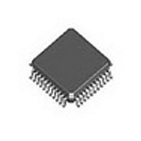
DJLXT360LE.A2 S E001 Intel, DJLXT360LE.A2 S E001 Datasheet - Page 9

DJLXT360LE.A2 S E001
Manufacturer Part Number
DJLXT360LE.A2 S E001
Description
Manufacturer
Intel
Datasheet
1.DJLXT360LE.A2_S_E001.pdf
(54 pages)
Specifications of DJLXT360LE.A2 S E001
Number Of Transceivers
1
Operating Supply Voltage (typ)
5V
Screening Level
Industrial
Mounting
Surface Mount
Operating Supply Voltage (min)
4.75V
Operating Supply Voltage (max)
5.25V
Operating Temperature (min)
-40C
Operating Temperature (max)
85C
Lead Free Status / RoHS Status
Not Compliant
1.1
Datasheet
1. Data pins change based on whether external data or internal QRSS mode is active. Clock pins remain the same in both
PLCC
PLCC
11
12
23
24
13
16
19
20
Hardware and Host modes.
5
9
1
2
3
4
6
7
8
Table 1. LXT360 Clock and Data Pins by Mode
Table 2. LXT360 Control Pins by Mode
Pin #
Pin #
QFP
10
13
31
32
QFP
2
7
39
41
42
43
15
19
24
25
3
4
5
Mode Dependent Signals
As shown in
according to the selected mode(s) of operation. These pins, associated signal names and operating
modes are summarized in
Unipolar/
Integrated T1/E1 LH/SH Transceiver for DS1/DSX-1 or PRI Applications — LXT360
Hardware Modes
Bipolar
LOS
TRSTE
JASEL
MODE
Bipolar Mode
EC1
EC2
RNEG
TPOS
TNEG
RPOS
QRSS
Figure
LOS/
QPD
External Data Modes
2, the LXT360 has various signal pins that change function (and name)
Unipolar/
Bipolar
LOS
Host Modes
Table 1
TRSTE
MODE
Low
INT
SDI
Unipolar Mode
QRSS
LOS/
QPD
and
INSBPV
RDATA
TDATA
BPV
Table
PLCC
28
25
17
18
26
27
1
2. LXT360 signals are described in
Pin #
RRING
TRING
MCLK
RCLK
TCLK
RTIP
TTIP
QFP
35
20
21
36
37
38
Bipolar Mode
Unipolar/
Hardware Modes
Bipolar
TAOS
RNEG
RPOS
NLOOP
RLOOP
LLOOP
EC3
EC4
QRSS Modes
QRSS
QRSS
INSLER
INSBPV
Unipolar/
Bipolar
Unipolar Mode
Host Modes
Table
NLOOP
RDATA
SCLK
CLKE
SDO
Low
BPV
CS
3.
QRSS
9


